Radar Level Device
Radar Level Device
In modern industrial process control, accurate level measurement is critical for inventory management, operational safety, and process efficiency. Among the various technologies available, the radar level device has emerged as a gold standard for both liquid and solid applications. Utilizing electromagnetic waves to determine the distance to a product surface, these instruments offer a non-contact solution that is largely unaffected by changes in temperature, pressure, or the presence of vapors.
This guide provides a comprehensive technical overview of Radar Level Meters, covering their operating principles, selection criteria, and practical installation requirements for engineering professionals.
Understanding Radar Measurement Principles
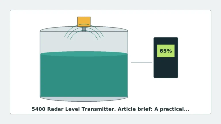
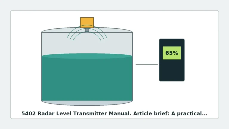
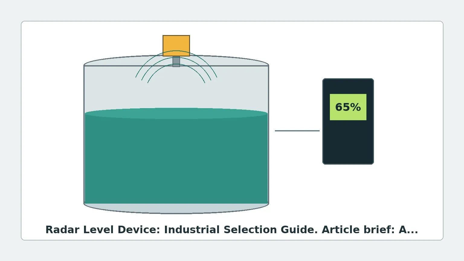
Before selecting a radar level device, it is essential to understand how these instruments interact with the process medium. Radar level measurement is based on the "Time of Flight" (ToF) principle. The device emits high-frequency electromagnetic pulses (typically in the microwave spectrum) that travel at the speed of light. When these waves encounter a medium with a different dielectric constant than the surrounding air or gas, a portion of the energy is reflected back to the sensor.
There are two primary methods used to process these signals:
1. Pulse Radar (Time of Flight)
Pulse radar instruments emit a short microwave pulse and then switch to receiving mode. The device measures the time elapsed between the emission and the reception of the reflected signal. Since the speed of light is constant, the distance (D) is calculated as:
*D = (Speed of Light × Time) / 2*
The level is then derived by subtracting this distance from the total vessel height.
2. FMCW (Frequency Modulated Continuous Wave)
FMCW radar does not send pulses but rather a continuous signal with a constantly changing frequency (a frequency sweep). The reflection from the product surface is received and mixed with the currently emitted signal. The frequency difference between the transmitted and received signals is directly proportional to the distance. FMCW is generally preferred for high-precision applications and environments with significant noise or turbulence.
Key Technology Variants
When evaluating a radar level device, engineers must choose between non-contacting and contacting (Guided Wave) technologies.
Non-Contact Radar
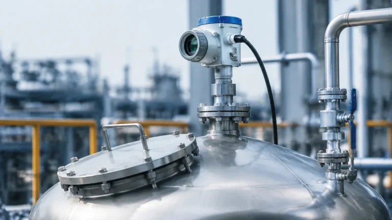
Non-contact radar level meters are mounted at the top of the tank and transmit signals through the air. They are ideal for corrosive, hygienic, or extremely hot materials because the sensor does not touch the medium. Modern units often operate at high frequencies, such as 26 GHz or 80 GHz. Higher frequencies allow for smaller antenna sizes and narrower beam angles, which help avoid internal tank obstructions like agitators or ladders.
Guided Wave Radar (GWR)
Guided Wave Radar uses a physical probe (a rod or cable) to guide the microwave signal to the liquid surface. This technology is highly effective for low-dielectric liquids (like oils and hydrocarbons) and applications where the liquid surface is turbulent or covered in foam. Because the energy is concentrated along the probe, GWR is less affected by tank geometry but requires the probe to be compatible with the chemical properties of the medium.
Selection Criteria for Industrial Applications
Selecting the correct radar level device requires a detailed analysis of the process environment. The following factors are decisive:
Dielectric Constant ($ε_r$)
The dielectric constant of the material is the most important factor in radar measurement. It determines how much energy is reflected.
- High $ε_r$ (>10): Water-based liquids provide strong reflections and are easy to measure.
- Low $ε_r$ (1.4 to 4): Hydrocarbons, solvents, and some solids reflect very little energy. These require high-sensitivity radar level meters or Guided Wave Radar to ensure a reliable signal.
Process Conditions
- Temperature: Standard sensors typically handle up to 150°C (302°F), but specialized high-temperature versions can withstand over 450°C (842°F) using ceramic seals and cooling fins.
- Pressure: For high-pressure reactors, devices rated for 40 bar (580 psi) or higher are required, often featuring secondary process seals to prevent leakage into the electronics housing.
- Vapors and Condensation: In applications with heavy steam or condensation, an 80 GHz radar with a PTFE-faced antenna is often recommended to prevent droplets from interfering with the signal.
Vessel Geometry
The presence of internal structures like heating coils, agitators, or baffles can create "false echoes." Narrow beam angles (achieved with higher frequencies or larger antennas) are essential in crowded tanks to ensure the radar "sees" the liquid surface rather than the tank hardware.
Selection Comparison Table
| Feature | Pulse Radar (26 GHz) | FMCW Radar (80 GHz) | Guided Wave Radar (GWR) |
| :— | :— | :— | :— |
| Accuracy | ±3 mm to ±5 mm | ±1 mm | ±2 mm |
| Measuring Range | Up to 30 m (98 ft) | Up to 120 m (393 ft) | Up to 60 m (196 ft) |
| Surface Conditions | Calm to moderate | Calm to moderate | Turbulent/Foamy |
| Dielectric Constant | ε_r > 1.9 | ε_r > 1.4 | ε_r > 1.4 |
| Obstructions | Moderate sensitivity | Low sensitivity | Immune (if probe is clear) |
| Best Use Case | General storage tanks | High-precision/Tall silos | Low dielectric/Interface |
Installation Considerations
Proper installation is critical to the performance of any radar level device. Engineering teams should adhere to the following guidelines:
1. Nozzle Dimensions: The antenna should ideally extend slightly beyond the bottom of the mounting nozzle to prevent signal interference from the nozzle edge. If the nozzle is long, a waveguide extension may be necessary.
2. Positioning: Avoid mounting the device in the center of a tank with a domed roof, as this can cause multiple reflections that confuse the sensor. The ideal position is usually 1/6th of the tank diameter from the wall.
3. Inflow Streams: Never install the radar level device directly above the filling inlet. The falling product will interfere with the radar signal and cause erratic readings.
4. Beam Path: Ensure the path of the radar beam is clear of obstructions. If an agitator is present, the device should be programmed with a "false echo suppression" map while the agitator is in motion to filter out the blades.
5. Orientation: For solids measurement, an aiming flange (swivel holder) is often required to align the sensor with the angle of repose of the material heap.
Limitations and Application Risks
While highly versatile, radar technology has specific limitations:
* Heavy Foam: Extremely thick, dense foam (like shaving cream) can absorb the radar signal entirely, resulting in a "lost echo" error. In these cases, Guided Wave Radar or ultrasonic sensors may be more effective, depending on the foam density.
* Dust: While radar penetrates dust better than ultrasonic sensors, extremely high dust concentrations in large grain silos can attenuate the signal of lower-frequency radars. 80 GHz units are generally better at penetrating dust due to their signal strength and focus.
* Vacuum Conditions: While radar works in a vacuum, the mechanical seals of the device must be specifically rated for vacuum service to prevent air ingress or sensor damage.
International Buyer Checklist
When sourcing a radar level device for global projects, procurement officers should confirm the following with the manufacturer:
* Certifications: Ensure the device carries necessary hazardous area certifications (ATEX, IECEx, or UL/CSA) if installed in explosive environments.
* Output Protocols: Most modern devices support 4-20mA HART, but Modbus RS485, Foundation Fieldbus, or Profibus may be required for integration into specific PLC/DCS architectures.
* Material Traceability: For chemical and pharmaceutical applications, request 3.1 material certificates for all wetted parts (e.g., 316L Stainless Steel, Hastelloy, or PTFE).
Frequently Asked Questions (FAQ)
Q: Can a radar level device measure the interface between two liquids?
A: Yes, Guided Wave Radar is particularly effective for interface measurement (e.g., oil and water). The signal reflects off the upper liquid layer and then continues through it to reflect off the lower liquid layer, provided the upper liquid has a lower dielectric constant.
Q: Does the color or transparency of the liquid affect the measurement?
A: No. Unlike optical sensors, radar is entirely unaffected by the color, transparency, or opacity of the medium.
Q: How often does a radar level meter need calibration?
A: Radar devices are solid-state and generally do not drift. Under stable conditions, they may only require a functional check every 1–2 years. However, if the dielectric constant of the medium changes significantly, the sensitivity settings might need adjustment.
Q: What is the minimum distance a radar can measure?
A: Every radar has a "blocking distance" (dead zone) near the antenna, typically 50 mm to 200 mm, where measurement is not possible. This must be accounted for when designing the tank's maximum fill level.
Conclusion
The implementation of a radar level device significantly enhances process reliability by providing non-contact, high-precision data. By understanding the dielectric properties of the medium and the physical constraints of the vessel, engineers can select a solution that minimizes maintenance and maximizes uptime. For complex applications involving extreme pressures or low-dielectric materials, consulting with a specialized manufacturer like Welk ensures that the selected Radar Level Meters are optimized for the specific industrial environment.