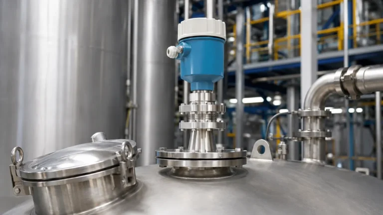
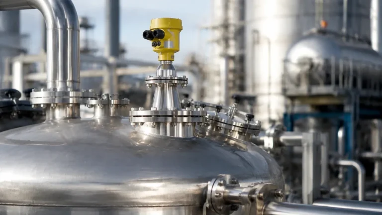
Radar Level Transmitter 3408a
Radar Level Transmitter 3408a: Engineering Principles and Application Guide
In the landscape of industrial process automation, the transition from contact-based measurement to non-contacting technologies has significantly reduced maintenance overhead and increased system reliability. Among the most versatile instruments in this category is the radar level transmitter 3408a. Designed to meet the rigorous demands of chemical processing, water treatment, and food and beverage production, this instrument leverages high-frequency electromagnetic waves to provide precise level data in challenging environments.
Selecting the correct instrumentation requires a deep understanding of the underlying physics, the specific constraints of the vessel, and the dielectric properties of the media. This guide examines the technical foundations of Radar Level Meters and provides a detailed engineering reference for the 3408a series.
1. Measurement Principles: FMCW vs. Pulsed Radar
Before implementing a radar level transmitter 3408a, engineers must distinguish between the two primary methods of radar measurement: Pulse Radar and Frequency Modulated Continuous Wave (FMCW).
Time of Flight (ToF) and Pulsed Radar
Traditional radar transmitters emit short microwave pulses toward the material surface. The instrument measures the "Time of Flight"—the interval between the emission of the pulse and the reception of the reflected echo. While effective, pulsed radar often requires a larger antenna to focus the beam and can struggle with low-dielectric materials or turbulent surfaces.
FMCW Technology in the 3408a
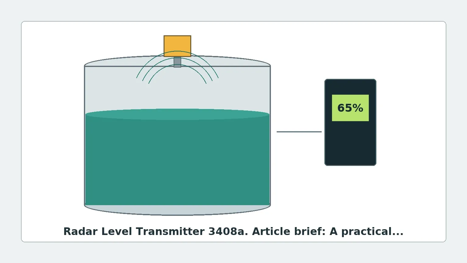
The radar level transmitter 3408a typically utilizes 80 GHz FMCW technology. In this method, the transmitter emits a continuous signal with a constantly changing frequency. As the signal travels to the product surface and back, the frequency of the emitted signal continues to change. When the reflected signal returns, it is compared to the signal being emitted at that exact moment. The difference in frequency (the frequency shift) is directly proportional to the distance.
Advantages of 80 GHz FMCW:
* Narrow Beam Angle: The high frequency allows for a very narrow beam (often as small as 3 degrees), which avoids internal tank obstructions like agitators or heating coils.
* High Resolution: FMCW provides superior accuracy, often within ±2 mm (0.08 inches), even over long ranges.
* Small Antenna Size: High-frequency waves can be focused using smaller process connections, such as 1-inch (25 mm) NPT or G threads.
2. Technical Specifications and Features of the 3408a
The 3408a is engineered as a "smart" transmitter, bridging the gap between robust industrial hardware and modern digital interfaces.
Key Performance Metrics
* Measuring Range: Capable of measuring distances up to 30 meters (approx. 98 feet) for liquids and slightly less for solids depending on dust concentration.
* Process Temperature: Standard units handle -40°C to +150°C (-40°F to 302°F).
* Process Pressure: Rated for vacuum up to 20 bar (290 psi), depending on the flange and seal selection.
* Frequency: 80 GHz W-band radar.
Digital Integration and Bluetooth
One of the defining features of the radar level transmitter 3408a is its integrated Bluetooth® connectivity. This allows commissioning and diagnostics to be performed via a smartphone or tablet using secure apps. This is particularly valuable for instruments mounted on top of tall silos or in hazardous areas where physical access is restricted. Additionally, it supports standard industrial protocols including 4-20 mA HART, allowing for seamless integration into existing PLC and SCADA systems.
3. Selection Criteria for Industrial Applications
Choosing the right configuration of a radar level transmitter 3408a depends on the physical and chemical properties of the media. Use the following table as a preliminary selection guide:
| Application Factor | Consideration for 3408a | Engineering Recommendation |
| :— | :— | :— |
| Dielectric Constant (DC) | Media with DC < 1.9 (e.g., oils, hydrocarbons) | Use a larger antenna or a stilling well to boost signal return. |
| Surface Turbulence | Rapid mixing or boiling liquids | Utilize the 3408a’s advanced signal filtering and damping settings. |
| Corrosive Media | Acids, bases, or saline solutions | Specify PTFE or PVDF wetted parts and encapsulated antennas. |
| Dust/Steam | Heavy vapor or pneumatic filling | 80 GHz signals penetrate steam better than ultrasonic waves but may require air purging for heavy dust. |
| Internal Obstructions | Ladders, pipes, or agitators | Leverage the narrow beam angle to "aim" between obstructions. |
4. Installation Guidelines and Constraints
Correct installation is the single most important factor in ensuring the longevity and accuracy of a radar level transmitter 3408a. Even the most advanced 80 GHz radar can fail if signal interference is not managed.
Nozzle Geometry
The height and diameter of the mounting nozzle (the standpipe) significantly impact performance. Ideally, the antenna should extend slightly past the bottom of the nozzle to prevent "ringing" or internal reflections. If a long nozzle is required, the 3408a’s software can be used to perform a "False Echo Suppression" to map out and ignore the nozzle reflection.
The 1/10 Rule
As a general rule of thumb, the transmitter should be mounted at a distance from the tank wall equal to at least 1/10th of the total tank height. This prevents the beam from reflecting off the wall or weld seams, which can create parasitic echoes.
Avoiding Obstructions
Despite the narrow beam of the 80 GHz radar level transmitter 3408a, it is vital to ensure the signal path is clear of:
1. Inflow Streams: Never mount the radar directly above the point where product enters the tank.
2. Agitator Blades: If the tank has a mixer, the radar should be positioned so the beam does not hit the blades. If this is unavoidable, the transmitter can be synchronized with the mixer via the PLC or use advanced software mapping to ignore the moving blades.
3. Vortexing: In high-speed mixing, the liquid surface may form a cone (vortex). The radar should be aimed at a flat portion of the surface to ensure a reliable return signal.
5. Limitations and Environmental Risks
While Radar Level Meters are highly versatile, they are not universal solutions. Engineers must be aware of specific limitations:
* Heavy Foam: While radar can penetrate light foam, dense, thick foam (like shaving cream) can absorb the microwave signal entirely, leading to a "Loss of Echo" (LoE) error. In such cases, a guided wave radar or a hydrostatic transmitter may be more appropriate.
* Vacuum Effects: While the vacuum itself does not affect the speed of the radar wave, the extreme temperature shifts often associated with vacuum processes can cause condensation on the antenna lens. An antenna with a flat PTFE face is recommended to minimize droplet buildup.
* Dielectric Minimums: If the material has an extremely low dielectric constant (e.g., liquefied gases), the signal may pass through the material and reflect off the bottom of the tank instead. High-sensitivity settings or stilling wells are mandatory here.
6. Maintenance and Troubleshooting
The radar level transmitter 3408a is virtually maintenance-free because it has no moving parts. However, periodic verification is recommended in regulated industries.
Common Troubleshooting Steps
* Signal Loss: Check for heavy buildup on the antenna lens. Even though 80 GHz radar is resistant to buildup, a thick layer of conductive material (like wet mud) can block the signal.
* Inaccurate Readings at High Levels: This is often caused by the "near-zone" effect or reflections from the mounting nozzle. Adjust the "Blanking Distance" (also known as the Dead Zone) to ignore the area immediately below the sensor.
* Fluctuating Values: This is usually due to surface turbulence. Increase the damping time in the transmitter settings to average out the readings.
7. Frequently Asked Questions (FAQ)
Q: Can the radar level transmitter 3408a be used for solids?
A: Yes, it is highly effective for solids like plastic pellets, grains, or powders. However, for materials with a high angle of repose (conical piles), an adjustable flange might be needed to aim the radar perpendicular to the slope of the material.
Q: How does the 3408a handle condensation?
A: The 80 GHz frequency uses a very small wavelength, and the 3408a often features a convex lens design that allows condensation to bead up and drip off, preventing signal attenuation.
Q: Is it safe for hazardous areas?
A: Most 3408a models carry global certifications such as ATEX, IECEx, and FM for use in Class I, Div 1 or Zone 0 environments. Always verify the specific certificate on the device nameplate before installation.
Conclusion
The radar level transmitter 3408a represents a significant advancement in non-contacting level measurement. By utilizing high-frequency 80 GHz FMCW technology, it offers the precision and narrow-beam capabilities required for complex industrial geometries. When selected with the correct wetted materials and installed according to best practices regarding nozzle placement and obstruction avoidance, it provides a highly reliable, low-maintenance solution for modern process control. For engineers seeking to optimize their level monitoring systems, understanding these technical nuances is the first step toward achieving operational excellence.