Radar Level Transmitter 3408
Radar Level Transmitter 3408: A Technical Guide for Industrial Applications
In the landscape of industrial process automation, the demand for precise, non-contact level measurement has led to the widespread adoption of high-frequency radar technology. The radar level transmitter 3408 represents a significant evolution in this field, designed to meet the rigorous demands of the chemical, water treatment, and oil and gas industries. This guide explores the engineering principles, selection criteria, and installation best practices for integrating these instruments into modern process control systems.
Measurement Principles: Frequency Modulated Continuous Wave (FMCW)
Before selecting a specific model like the radar level transmitter 3408, it is essential to understand the underlying technology. Most modern Radar Level Meters utilize Frequency Modulated Continuous Wave (FMCW) technology, which offers superior accuracy compared to older pulse-based systems.
How FMCW Works
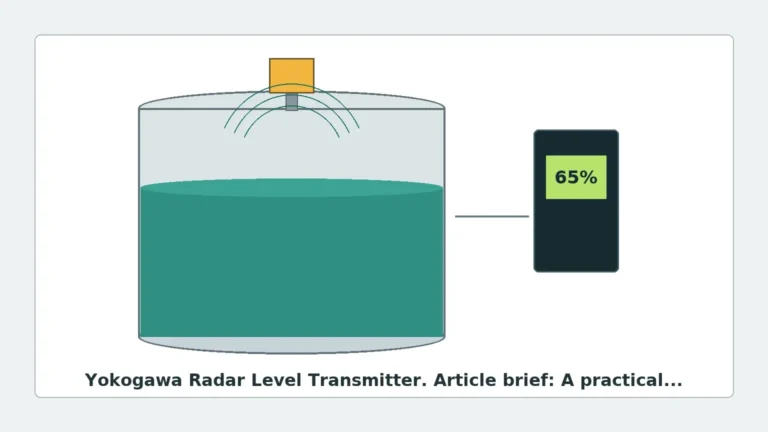
In an FMCW radar system, the transmitter emits a continuous signal with a frequency that varies linearly over time (the sweep). This signal travels to the surface of the medium and is reflected back to the antenna. Because the transmitter is constantly changing its frequency, there is a measurable difference between the frequency currently being transmitted and the frequency of the signal that has just returned.
This frequency difference ($Δf$) is directly proportional to the time of flight, and therefore, the distance to the product surface. The relationship is defined by the formula:
$$d = \frac{c \cdot \Delta f}{2 \cdot S}$$
Where:
* d is the distance to the surface.
* c is the speed of light.
* Δf is the frequency difference.
* S is the frequency sweep rate (slope).
The 80 GHz Advantage
The radar level transmitter 3408 typically operates in the 80 GHz frequency band. Compared to lower frequency radars (such as 6 GHz or 26 GHz), 80 GHz technology provides a much narrower beam angle. This allows the signal to avoid internal tank obstructions like agitators, heating coils, and baffles, which frequently cause false echoes in lower-frequency devices.
Key Features of the Radar Level Transmitter 3408
The 3408 series is engineered for versatility and ease of use in complex industrial environments. Its design focuses on reducing the total cost of ownership through simplified commissioning and robust performance.
1. High Dynamic Range: This allows the transmitter to track levels even when the signal strength is weakened by surface turbulence, foam, or low-dielectric constant liquids.
2. Smart Diagnostics: Many versions of the 3408 include onboard health monitoring and data logging, allowing maintenance teams to identify issues like antenna coating or signal interference before they lead to process downtime.
3. User-Friendly Interface: Modern transmitters often feature Bluetooth connectivity or intuitive local displays, enabling configuration without opening the housing—a critical safety feature in hazardous areas.
4. Process Compatibility: With a range of antenna materials (such as PTFE or PEEK) and process connections (flanged or threaded), the device can be adapted to corrosive or hygienic environments.
Selection Criteria for Industrial Level Measurement
Choosing the correct configuration for a radar level transmitter 3408 requires a thorough analysis of the process environment. Engineers should consult the following selection table to align instrument specifications with application needs.
Selection Matrix
| Parameter | Requirement | Consideration for 3408 |
| :— | :— | :— |
| Medium State | Liquid, Slurry, or Solid | 80 GHz is excellent for liquids; specific antenna shapes may be needed for solids to handle dust. |
| Dielectric Constant (εr) | Low (εr < 2.0) to High (εr > 10) | Lower εr values reflect less energy. FMCW sensitivity is crucial for oils and hydrocarbons. |
| Process Temperature | -40°C to +150°C (-40°F to 302°F) | Ensure the antenna material and seals (Viton, EPDM, etc.) match the temperature profile. |
| Process Pressure | Vacuum to 40 bar (580 psi) | Check flange ratings and pressure-tight feedthroughs. |
| Measurement Range | Up to 30m (98 ft) or more | Verify the signal-to-noise ratio at the maximum required distance. |
| Accuracy | ±1 mm to ±3 mm | Critical for inventory management and high-precision dosing. |
Installation Considerations and Constraints
Proper installation is the most critical factor in ensuring the long-term reliability of a radar level transmitter 3408. Even the most advanced sensor will fail to provide accurate data if positioned incorrectly.
Mounting Location
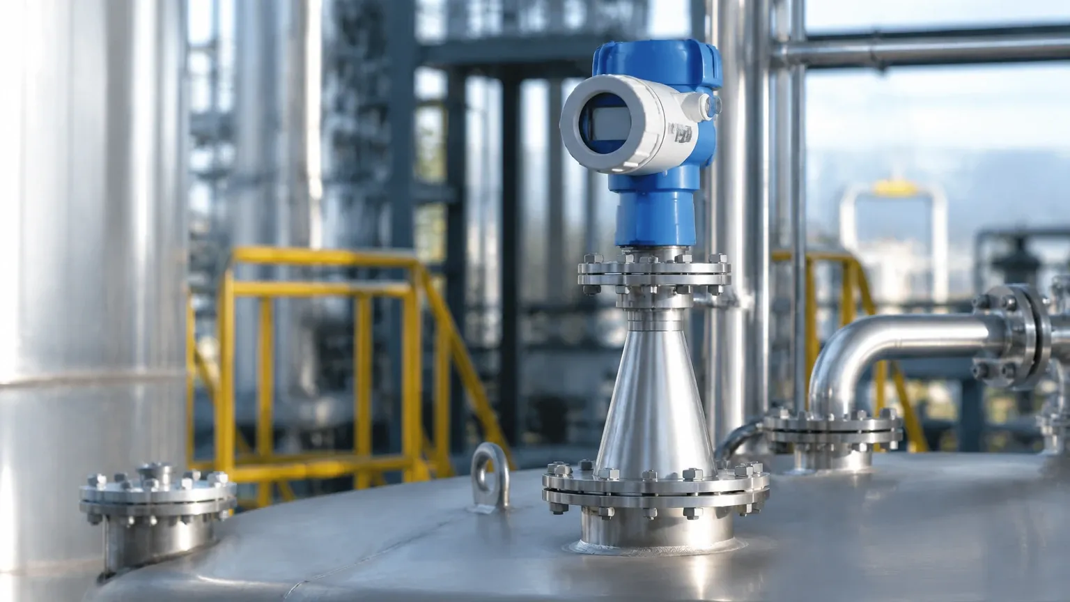
* Avoid the Center: Never mount the transmitter in the exact center of a tank with a domed top. This can cause multiple reflections that interfere with the primary signal.
* Nozzle Height: The antenna should ideally extend slightly beyond the bottom of the mounting nozzle to prevent "ringing" or signal interference from the nozzle walls.
* Inflow Avoidance: Do not install the sensor directly above the tank's filling inlet. The turbulence and falling material will create significant signal noise.
Beam Angle and Obstructions
The narrow beam of an 80 GHz radar (often as small as 3 degrees) provides more flexibility than older models. However, engineers must still ensure that the "signal cone" remains clear of obstructions. If a ladder or pipe is within the beam's path, the transmitter must be configured with a "False Echo Suppression" or "Empty Tank Mapping" routine to ignore these static reflections.
Metric and Imperial Clearances
For a standard 80 GHz transmitter with a 40 mm (1.5 in) antenna, a typical clearance of 200 mm (8 in) from the tank wall is recommended to avoid side-wall reflections. In tall, narrow silos, this clearance becomes even more vital.
Application Risks and Limitations
While the radar level transmitter 3408 is highly versatile, certain process conditions present risks to measurement accuracy:
1. Heavy Foam: While radar can penetrate some foam, thick, dense foam (especially in chemical detergents or fermentation) can absorb the radar signal entirely. In such cases, a guided wave radar or hydrostatic sensor might be more appropriate.
2. Condensation and Build-up: Although 80 GHz radar handles light condensation well, heavy coating on the antenna lens can attenuate the signal. Models with integrated air purge connections or PTFE drip-off lenses are recommended for these environments.
3. Extremely Low Dielectric Media: Liquefied gases or pure hydrocarbons with a dielectric constant below 1.5 may not reflect enough energy for a standard non-contact radar. A stilling well can be used to concentrate the signal and improve reflection.
Maintenance and Troubleshooting
Industrial radar level meters are generally low-maintenance because they have no moving parts. However, a routine check-up schedule should include:
* Visual Inspection: Check for physical damage to the housing or antenna lens.
* Signal Quality Check: Monitor the "Signal-to-Noise Ratio" (SNR) via the transmitter's diagnostic menu. A declining SNR often indicates lens coating or a failing electronics module.
* Cleaning: If the application involves heavy vapors or crystallization, the antenna lens should be cleaned periodically with a soft cloth and compatible solvent. Do not use abrasive materials that could scratch the PTFE surface.
Frequently Asked Questions (FAQ)
Q: Can the radar level transmitter 3408 measure through a plastic tank wall?
A: Yes, because plastic (like PE or PP) is transparent to radar signals, the transmitter can be mounted outside the tank to measure the level through the roof, provided the material is not conductive and the thickness is within reasonable limits (typically <10mm).
Q: How does the 3408 handle internal agitators?
A: The narrow beam of the 80 GHz signal often allows the radar to "miss" the agitator blades. If the blades do cross the beam, the software's echo tracking algorithms can usually distinguish between the moving agitator and the relatively slow-moving liquid surface.
Q: Is calibration required upon installation?
A: Basic configuration (setting the zero and span points) is required. However, unlike hydrostatic sensors, radar does not require wet calibration. You can set the measurement parameters using the tank height and desired offset without filling the vessel.
Conclusion
The radar level transmitter 3408 is a robust solution for a wide variety of industrial level measurement challenges. By leveraging FMCW technology and the narrow beam characteristics of the 80 GHz band, it provides high-precision data even in difficult process conditions. For international buyers and engineers, success lies in matching the transmitter’s specifications to the specific dielectric, temperature, and physical constraints of the application. For further information on hardware options and technical support, users can explore various Radar Level Meters to find the optimal fit for their automation infrastructure.