Radar Level Transmitter Frequency
Radar Level Transmitter Frequency: A Technical Engineering Guide
In industrial process automation, the selection of level measurement instrumentation is critical for operational safety, inventory accuracy, and process efficiency. Among the various technologies available, non-contact radar has emerged as a premier solution due to its lack of moving parts and resistance to changes in pressure, temperature, and vapor composition. However, the performance of these instruments is fundamentally dictated by the operating frequency. Understanding the nuances of radar level transmitter frequency is essential for engineers and procurement professionals when specifying equipment for complex industrial environments.
Modern Radar Level Meters typically operate within three primary frequency bands: 6 GHz (C-band), 26 GHz (K-band), and 80 GHz (W-band). Each frequency range offers distinct advantages and limitations regarding beam divergence, sensitivity to surface conditions, and ability to penetrate atmospheric interference.
Measurement Principles and the Role of Frequency
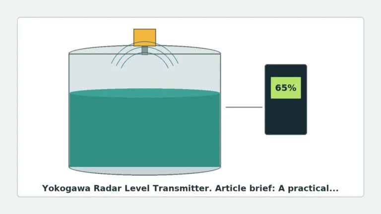
Radar level measurement relies on the transmission of electromagnetic waves toward a target material and the detection of the reflected signal. The distance is calculated based on the time it takes for the signal to travel to the surface and back. There are two primary methods used in industrial radar: Time of Flight (ToF) and Frequency Modulated Continuous Wave (FMCW).
Time of Flight (Pulse Radar)
In pulse radar, the transmitter emits a short microwave pulse and measures the elapsed time until the echo is received. The frequency of these pulses determines the energy and wavelength of the signal. Lower frequencies have longer wavelengths, which interact differently with surface turbulence and foam than higher frequencies.
Frequency Modulated Continuous Wave (FMCW)
FMCW radar transmits a continuous signal with a constantly changing frequency (a sweep). The distance is determined by the frequency difference between the transmitted and received signals at any given moment. The bandwidth of this sweep is directly related to the resolution of the measurement. Higher center frequencies often allow for wider bandwidths, resulting in significantly higher precision.
The Relationship Between Frequency and Beam Angle
The beam angle ($ heta$) of a radar antenna is inversely proportional to the frequency ($f$) and the antenna diameter ($D$). The approximate relationship can be expressed as:
$$\theta \approx \frac{k \cdot c}{f \cdot D}$$
Where $c$ is the speed of light and $k$ is a constant. In practical terms, this means that at a fixed antenna size, increasing the frequency results in a narrower, more focused beam. This focus is critical for avoiding internal tank obstructions like agitators, ladders, or heating coils.
Comparison of Common Radar Frequencies
6 GHz (C-Band) Radar
Historically one of the first frequencies used for industrial radar, 6 GHz remains relevant for specific niche applications. Its long wavelength (approximately 50 mm / 1.97 in) allows the signal to penetrate heavy foam, steam, and dust more effectively than higher frequencies.
* Advantages: Excellent performance in heavy condensation and foam; highly robust against atmospheric turbulence.
* Disadvantages: Very wide beam angle (typically 20° to 30°), requiring large antennas (DN150/6" or larger) to achieve even moderate focus. Not suitable for small tanks or vessels with internal obstructions.
26 GHz (K-Band) Radar
Often referred to as the "workhorse" of the industry, 26 GHz radar offers a balance between beam focus and signal robustness. With a wavelength of approximately 12 mm (0.47 in), it provides sufficient sensitivity for most liquid and solid applications.
* Advantages: Moderate beam angle (8° to 12° with a DN80/3" antenna); capable of measuring materials with lower dielectric constants than 6 GHz units.
* Disadvantages: Can be affected by heavy foam or extremely thick steam; requires careful mounting to avoid false echoes from vessel walls in narrow tanks.
80 GHz (W-Band) Radar
80 GHz technology represents the current state-of-the-art in radar level measurement. Its short wavelength (approximately 3.75 mm / 0.15 in) and high frequency allow for extreme precision and very narrow beam angles.
* Advantages: Narrow beam angles (as low as 3°); small antenna sizes (down to DN25/1"); high dynamic range for measuring low-dielectric materials like plastic pellets or oils; ability to measure through plastic tank tops.
* Disadvantages: Higher sensitivity to heavy surface foam; higher cost in some configurations (though this is narrowing).
Technical Selection Table
| Feature | 6 GHz (C-Band) | 26 GHz (K-Band) | 80 GHz (W-Band) |
| :— | :— | :— | :— |
| Wavelength | ~50 mm | ~12 mm | ~3.75 mm |
| Typical Beam Angle (DN80) | ~25° | ~10° | ~3° |
| Measurement Accuracy | ±5 mm to ±10 mm | ±2 mm to ±5 mm | ±1 mm |
| Foam Penetration | Excellent | Moderate | Limited |
| Dust/Steam Resistance | High | Moderate | High (due to signal strength) |
| Small Tank Suitability | Poor | Good | Excellent |
| Solid Material Handling | Limited | Good | Excellent |
| Min. Dielectric Constant ($\varepsilon_r$) | > 2.0 | > 1.6 | > 1.1 |
Engineering Considerations for Frequency Selection
1. Internal Obstructions and Beam Path
When a vessel contains internal structures such as agitator blades, baffles, or cooling pipes, a narrow beam is mandatory. A 26 GHz or 80 GHz radar level transmitter frequency is preferred here. If the beam hits an obstruction, it creates a "false echo" that may be stronger than the actual product level, leading to measurement errors. While software "false echo suppression" can ignore these, it is always better to avoid the obstruction entirely through high-frequency beam focusing.
2. Nozzle Geometry
The mounting nozzle acts as a waveguide. For low-frequency radars, the nozzle must be wide and short to prevent the signal from reflecting off the nozzle walls. High-frequency 80 GHz radars can be mounted on much longer and narrower nozzles (e.g., a 500 mm / 19.7 in long nozzle on a DN50 / 2" flange) without signal degradation.
3. Material Properties (Dielectric Constant)
The Dielectric Constant ($\varepsilon_r$) of the medium determines how much energy is reflected back to the sensor. Materials with low $\varepsilon_r$ (like hydrocarbons, solvents, or dry powders) reflect very little energy. 80 GHz transmitters generally have a higher dynamic range and better signal-to-noise ratios, making them superior for measuring low-dielectric media.
4. Surface Conditions: Turbulence and Foam
* Turbulence: Agitated surfaces scatter radar signals. Higher frequencies are more sensitive to this scattering, but their high update rates and advanced algorithms usually compensate for it.
* Foam: Foam is a complex medium. Dry, light foam may be transparent to 6 GHz and 26 GHz radar, allowing measurement of the liquid below. Thick, wet foam may reflect the signal, causing the radar to measure the top of the foam. In extreme foam cases, 6 GHz is often the only reliable choice.
Installation and Maintenance Guidelines
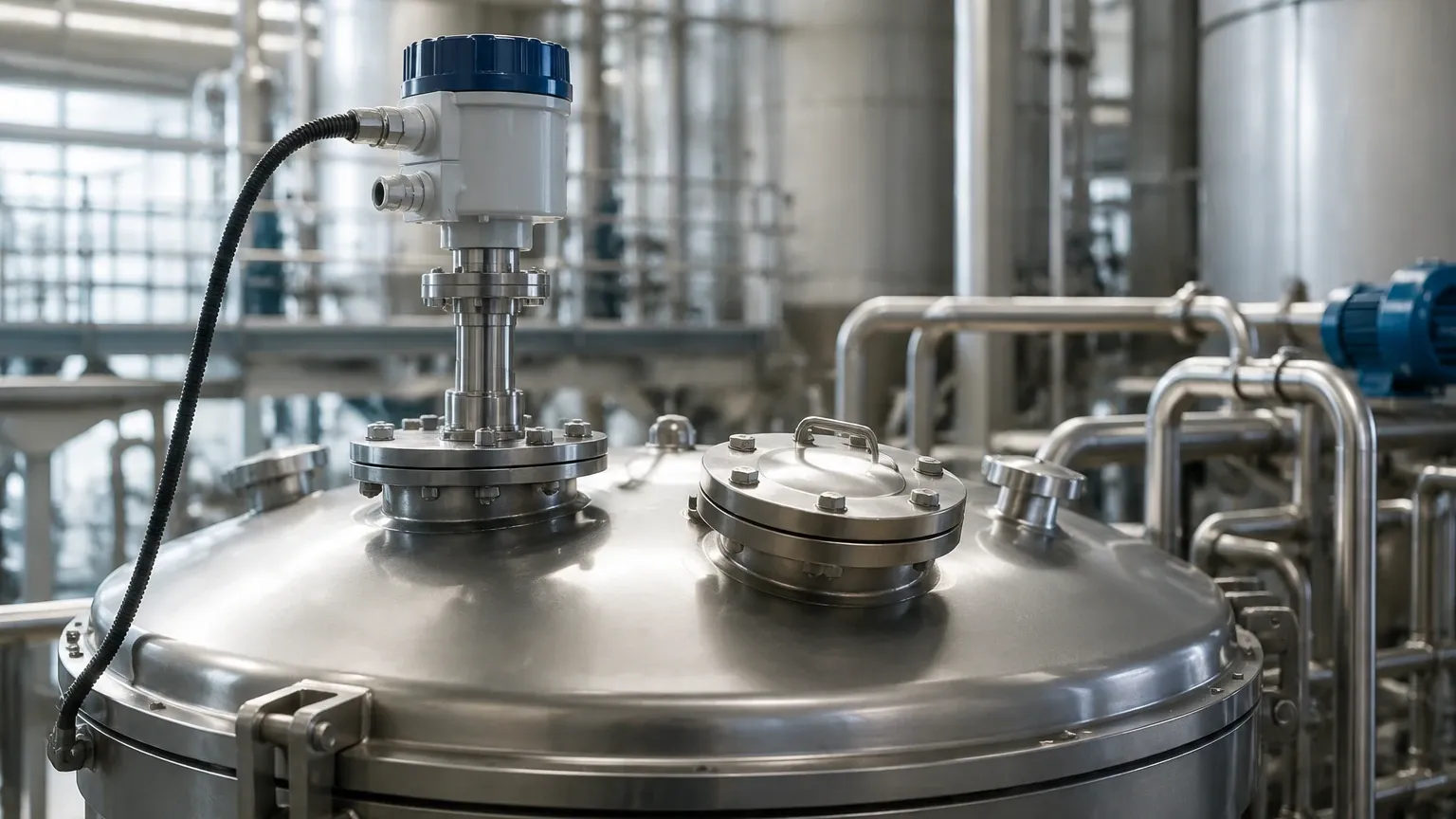
To ensure the selected radar level transmitter frequency performs as expected, follow these installation best practices:
* Orientation: Ensure the antenna is perpendicular to the product surface. For solids, an aiming flange (swivel mount) is often required to align the sensor with the angle of repose.
* Distance from Wall: Always maintain a minimum distance from the vessel wall, typically 1/10th of the tank height, to prevent interference, especially with 6 GHz and 26 GHz units.
* Nozzle Clearance: The antenna should ideally extend slightly past the bottom of the mounting nozzle to prevent "ringing" or internal reflections within the nozzle.
* Environmental Protection: In outdoor installations, use a sunshade to prevent temperature-induced electronics drift and ensure the cable glands are properly sealed against moisture.
Limitations and Risk Mitigation
While radar is highly versatile, it is not a "one-size-fits-all" solution. Engineers should be aware of the following risks:
* Antenna Buildup: In applications with crystallizing vapors or sticky dust, material can build up on the antenna lens. While 80 GHz units often feature flush-mounted PFA lenses that resist buildup, significant accumulation will eventually attenuate the signal. Air purging systems should be considered for these environments.
* Vacuum and High Pressure: While the radar signal itself is unaffected by vacuum, the mechanical seal of the antenna must be rated for the process pressure. Ensure the transmitter's process connection matches the vessel's pressure rating.
* Multiple Reflections: In small, spherical, or horizontal cylindrical tanks, the radar signal may bounce multiple times off the walls (multipath interference). High-frequency radar with a narrow beam significantly reduces this risk.
Frequently Asked Questions (FAQ)
Q: Is a higher frequency always better for level measurement?
A: Not necessarily. While 80 GHz offers better precision and smaller beams, 6 GHz is still superior for applications with extremely heavy foam or very thick steam where higher frequencies might be absorbed or scattered.
Q: Can I use an 80 GHz radar to measure through a plastic tank lid?
A: Yes. One of the unique advantages of 80 GHz is that the wavelength is small enough to pass through many non-conductive plastics (like HDPE or PP) with minimal attenuation, allowing for completely non-invasive measurement from outside the tank.
Q: How does frequency affect the measurement of solids?
A: For solids, higher frequency is almost always better. The narrow beam avoids the vessel walls, and the high sensitivity allows for better detection of the diffuse reflections from sloped or uneven surfaces (the angle of repose).
Q: Does the frequency affect the safety rating (SIL) of the device?
A: The frequency itself does not determine the Safety Integrity Level (SIL). SIL ratings are based on the reliability of the electronics, software, and diagnostic capabilities of the specific transmitter model.
Conclusion
Selecting the correct radar level transmitter frequency is a fundamental step in process instrumentation design. By matching the frequency—6 GHz, 26 GHz, or 80 GHz—to the specific physical constraints of the vessel and the dielectric properties of the medium, engineers can ensure long-term measurement stability. For most modern liquid and solid applications, 80 GHz provides the highest versatility, but 26 GHz remains a cost-effective and reliable standard for general-purpose use. When facing extreme foam or steam, the traditional 6 GHz C-band remains an essential tool in the engineer's kit.