Radar Level Transmitter Formula
Radar Level Transmitter Formula: A Technical Guide to Non-Contact Measurement
In the field of industrial process control, the demand for precise, non-contact level measurement has led to the widespread adoption of radar technology. Understanding the underlying radar level transmitter formula is essential for engineers and procurement specialists to ensure that the selected instrumentation meets the specific requirements of their application. Whether managing volatile chemicals, wastewater, or bulk solids, the mathematical principles governing these devices dictate their accuracy, range, and reliability.
Radar Level Meters utilize electromagnetic waves to determine the distance to a product surface. Unlike ultrasonic sensors, which rely on sound waves and are susceptible to air temperature and pressure changes, radar signals travel at the speed of light and remain largely unaffected by the vapor space environment. This article provides a comprehensive breakdown of the formulas, selection criteria, and installation best practices for radar level transmitters.
1. Fundamental Measurement Principles
Before diving into specific formulas, it is necessary to distinguish between the two primary technologies used in radar level measurement: Pulse Radar and Frequency Modulated Continuous Wave (FMCW).
Pulse Radar (Time of Flight)
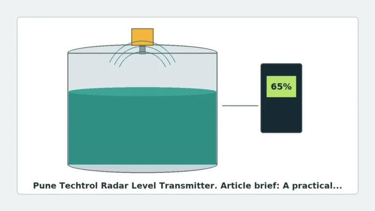
Pulse radar transmitters emit a short microwave signal toward the medium. The signal reflects off the surface and returns to the sensor. The device measures the time elapsed between transmission and reception. This is known as the Time of Flight (ToF) principle.
FMCW (Frequency Modulated Continuous Wave)
FMCW radar transmits a continuous signal with a constantly changing frequency (a frequency sweep). When the reflected signal is received, it is compared to the signal being transmitted at 그 moment. The difference in frequency (the "beat frequency") is directly proportional to the distance the signal has traveled. FMCW is generally preferred for high-precision applications due to its superior signal-to-noise ratio.
2. The Core Radar Level Transmitter Formula
To calculate the level of a medium in a tank, the transmitter must first determine the distance from the sensor reference point to the surface.
The Distance Formula
The basic formula for distance in a Pulse Radar system is:
$$D = \frac{c \times t}{2}$$
Where:
* D = Distance from the sensor to the material surface (meters).
* c = Speed of light in the medium (approximately $299,792,458$ m/s in a vacuum/air).
* t = Transit time (the total time taken for the pulse to travel to the surface and back, measured in seconds).
Because the signal travels to the surface and back, the product of speed and time must be divided by two to find the one-way distance.
The Level Calculation Formula
Once the distance ($D$) is known, the actual level ($L$) of the material is calculated based on the known geometry of the vessel:
$$L = H – D$$
Where:
* L = Level of the product (meters).
* H = Tank height or the distance from the sensor reference point to the bottom of the tank (zero level).
FMCW Beat Frequency Formula
For FMCW systems, the distance is derived from the frequency shift ($f_b$):
$$f_b = \frac{S \times 2 \times D}{c}$$
Rearranging for Distance ($D$):
$$D = \frac{f_b \times c}{2 \times S}$$
Where:
* $f_b$ = Beat frequency (Hz).
* S = Sweep rate or bandwidth (change in frequency over time, Hz/s).
* c = Speed of light.
This radar level transmitter formula demonstrates why higher bandwidths (sweep rates) allow for higher resolution and accuracy in FMCW sensors.
3. Factors Influencing Measurement Accuracy
While the formulas above provide the theoretical basis, several physical factors influence the accuracy of the measurement in a real-world industrial environment.
Dielectric Constant ($\\epsilon_r$)
The reflectivity of a material is determined by its dielectric constant. Materials with high dielectric constants (e.g., water, $\epsilon_r \approx 80$) reflect radar signals very well. Materials with low dielectric constants (e.g., hydrocarbons, $\epsilon_r < 2.5$) allow much of the signal to penetrate the surface, resulting in a weaker return echo. If the dielectric constant is extremely low, the signal may reflect off the tank bottom instead of the surface, leading to measurement errors.
The Beam Angle
The frequency of the radar transmitter determines the beam angle. Higher frequencies (such as 80 GHz) produce a narrower beam compared to lower frequencies (6 GHz or 26 GHz). A narrower beam is less likely to hit internal tank obstructions like agitators, ladders, or heating coils.
4. Selection Criteria for Radar Level Meters
Choosing the right instrument requires balancing technical requirements with budget constraints. The following table summarizes the typical selection parameters for different radar types.
| Feature | 6 GHz Radar | 26 GHz Radar | 80 GHz Radar |
| :— | :— | :— | :— |
| Beam Angle | Wide (approx. 20-30°) | Medium (approx. 8-12°) | Narrow (approx. 3-4°) |
| Accuracy | $\pm$ 10-30 mm | $\pm$ 2-5 mm | $\pm$ 1 mm |
| Application | Heavy steam, foam, turbulence | General process liquids | Small tanks, solids, high precision |
| Antenna Size | Large | Medium | Small |
| Obstruction Tolerance | Low | Moderate | High |
When to use 80 GHz Technology
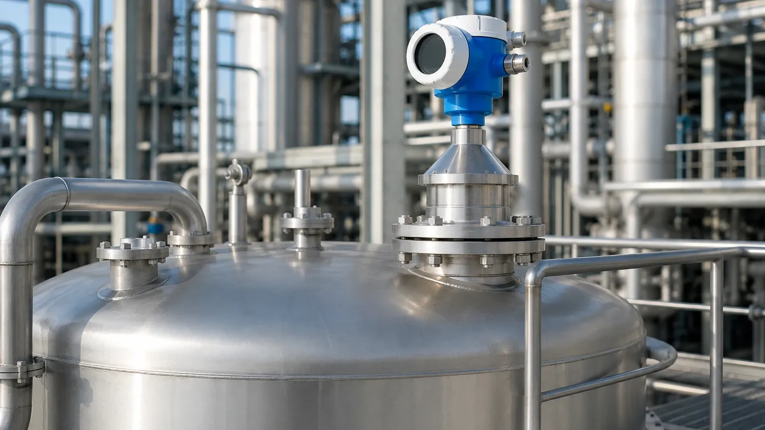
In modern industrial automation, 80 GHz Radar Level Meters have become the standard for difficult applications. The narrow beam allows for installation in small nozzles and prevents interference from tank walls. Furthermore, the higher frequency provides better performance in dusty environments (solids) and is less affected by condensation on the antenna.
5. Installation Considerations and Constraints
Correct installation is as critical as the mathematical accuracy of the sensor. Even the most precise radar level transmitter formula cannot compensate for a poorly positioned device.
Blocking Distance (Dead Zone)
Every radar sensor has a "blocking distance" near the antenna where measurement is not possible. This is typically between 50 mm and 500 mm, depending on the model. The maximum expected level in the tank must remain below this dead zone to avoid "high-level" lock-in errors.
Nozzle Geometry
The mounting nozzle should be as short as possible. If the nozzle is too long or narrow, it can create internal reflections (ringing) that mask the true surface echo. For 26 GHz and 80 GHz sensors, the antenna should ideally extend slightly past the bottom of the nozzle.
Avoiding Obstructions
The radar beam must have a clear path to the surface. If an obstruction (like a support beam) is unavoidable, many modern transmitters offer "False Echo Suppression" software. This allows the user to map out static reflections so the transmitter ignores them, focusing only on the moving surface level.
Stills Wells and Bypass Pipes
In applications with heavy foam or extreme turbulence, installing the radar inside a stilling well (a perforated pipe) or a bypass chamber can stabilize the surface and provide a much cleaner signal return. This is common in the oil and gas industry for crude oil storage.
6. Application Risks and Limitations
Despite their versatility, radar level transmitters face specific challenges:
1. Heavy Foam: While radar can penetrate some foam, extremely dense, conductive foam (like that found in some chemical detergents) can absorb the radar signal entirely, leading to signal loss.
2. Vacuum Conditions: While radar works in a vacuum, the speed of light ($c$) changes slightly depending on the gas composition and pressure in the vapor space. In most industrial applications, this change is negligible, but in high-pressure gas phases (e.g., high-pressure CO2), a correction factor may be required.
3. Multiple Interfaces: If a tank contains two liquids (e.g., oil on top of water), a standard non-contact radar will usually measure the top surface. Measuring the interface between the two requires specialized Guided Wave Radar (GWR).
7. Frequently Asked Questions (FAQs)
Q: Does the pressure inside the tank affect the radar level transmitter formula?
A: In most cases, no. Electromagnetic waves do not require a medium to travel. However, at extremely high pressures (e.g., >50 bar) with specific gases, the dielectric constant of the gas phase increases, which slightly slows down the signal. This can result in a small measurement offset that requires compensation.
Q: Can I use a radar level meter for solids?
A: Yes. However, solids often have an uneven surface (angle of repose) and lower dielectric constants than liquids. High-frequency 80 GHz radars are preferred for solids because their narrow beam can be aimed at specific points, and they handle the weak reflections from dust better.
Q: How do I verify the accuracy of the radar level transmitter formula in the field?
A: Field verification is typically done by comparing the transmitter reading against a manual dip tape measurement. It is important to ensure the manual measurement is taken from the same reference point as the sensor.
Q: What information should an international buyer provide to a manufacturer like Welk?
A: To receive an accurate recommendation, provide the following:
* Medium name and dielectric constant.
* Process temperature and pressure.
* Tank height and nozzle dimensions.
* Presence of agitators or foam.
* Required output signal (e.g., 4-20mA HART, Modbus, or Profibus).
Conclusion
The radar level transmitter formula is the foundation of one of the most reliable measurement technologies available today. By understanding how distance, time, and frequency interact, engineers can better troubleshoot their systems and select the most cost-effective instrumentation for their needs.
For high-performance applications, Welk provides a range of Radar Level Meters designed to withstand harsh industrial environments while delivering millimeter-level precision. When selecting equipment, always prioritize the frequency and antenna design that best match your specific tank geometry and material properties to ensure long-term, maintenance-free operation.