Radar Level Transmitter Specification
Radar Level Transmitter Specification: A Comprehensive Engineering Guide
In the landscape of industrial process control, the accuracy and reliability of level measurement are paramount. Among the various technologies available, radar-based systems have emerged as the gold standard for non-contact measurement in challenging environments. However, achieving optimal performance requires a meticulous approach to the radar level transmitter specification. Selecting the wrong frequency, antenna type, or mounting position can lead to signal loss, false readings, and process downtime.
This guide provides a technical deep dive into the specifications of Radar Level Meters, exploring their operating principles, key performance parameters, and the critical factors that engineers must define during the procurement and design phases.
Understanding Radar Measurement Principles
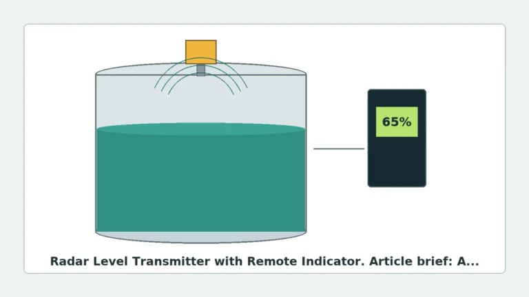
Before detailing a radar level transmitter specification, it is essential to understand how these instruments interact with the process medium. Radar level transmitters operate on the Time of Flight (ToF) principle, where electromagnetic pulses are emitted, reflected off the material surface, and received by the sensor. The distance is calculated based on the time interval and the constant speed of light.
There are two primary modulation techniques used in modern industrial radar:
1. Pulse Radar
Pulse radar emits short microwave bursts and measures the time it takes for the pulse to return. This technology is often used in battery-powered or loop-powered devices due to its lower power consumption. While effective for many applications, it may struggle with low-dielectric materials or extremely turbulent surfaces where the signal-to-noise ratio is low.
2. Frequency Modulated Continuous Wave (FMCW)
FMCW radar transmits a continuous signal with a constantly changing frequency (a frequency sweep). The reflected signal is compared to the transmitted signal at that moment, and the frequency difference (the "beat frequency") is directly proportional to the distance. FMCW provides significantly higher resolution and better signal processing capabilities, making it the preferred choice for high-precision radar level transmitter specification in complex tank geometries.
The Role of Frequency in Specification
The operating frequency of a radar transmitter determines its beam angle, sensitivity, and ability to penetrate dust or steam. When specifying a device, the choice of frequency is often the most critical decision.
| Frequency Band | Typical Beam Angle | Primary Applications | Strengths | Limitations |
| :— | :— | :— | :— | :— |
| 6 GHz (C-Band) | 20° – 30° | Large tanks, heavy foam, steam | High penetration through heavy condensation/foam. | Large antenna required; wide beam picks up internal obstructions. |
| 26 GHz (K-Band) | 8° – 12° | Standard liquid storage, chemical tanks | Good balance of size and accuracy; versatile for most liquids. | Affected by heavy foam; requires larger nozzles than 80GHz. |
| 80 GHz (W-Band) | 3° – 6° | Small vessels, solids, high-precision liquids | Extremely narrow beam; ignores obstacles; very small process connections. | Higher cost; can be attenuated by extremely thick steam or dust. |
Key Technical Specifications for Engineering Selection
When drafting a radar level transmitter specification for a project, the following parameters must be defined to ensure the instrument is fit for purpose.
1. Measurement Range and Accuracy
Industrial radar units can measure ranges from a few centimeters up to 120 meters. Accuracy typically ranges from ±1 mm for high-precision custody transfer applications to ±10 mm for general process monitoring. It is vital to specify the required accuracy across the entire measuring range, as some sensors lose precision near the antenna (the "dead zone").
2. Dielectric Constant (εr)
The dielectric constant of the medium determines how much energy is reflected. Water has a high εr (~80) and is easy to measure. Hydrocarbons, oils, and some solids have low εr (<2.0), which reflects very little energy. If the medium has a low dielectric constant, the specification must include high-sensitivity electronics or a guided wave radar (GWR) alternative.
3. Process Temperature and Pressure
Radar electronics are sensitive to heat. While the antenna (the wetted part) can be designed to withstand temperatures exceeding 250°C (482°F) and pressures up to 40 bar (580 psi) or more, the housing containing the transmitter must be kept within its operating limits. High-temperature applications require the specification of cooling fins or standoff pipes.
4. Antenna Type and Material
The antenna is the interface between the instrument and the process. Common types include:
* Horn Antennas: Standard for 26GHz units; available in various diameters to control beam angle.
* Lens Antennas: Common in 80GHz units; flush-mounted and resistant to buildup.
* Parabolic Antennas: Used for long-range solids measurement where a high-gain signal is needed.
* Wetted Materials: Typically 316L Stainless Steel, but corrosive environments may require PTFE, Hastelloy, or Tantalum coatings.
Installation Considerations and Constraints
A technically perfect radar level transmitter specification can still fail if installation constraints are ignored. The following engineering rules apply:
* Nozzle Geometry: The radar beam must clear the bottom edge of the mounting nozzle. If the nozzle is too long or narrow, the radar will detect the nozzle edge as the level. This is particularly important for 6GHz and 26GHz units with wider beam angles.
* Obstruction Clearance: Agitators, ladders, and heating coils act as reflectors. The instrument should be mounted such that the signal beam (defined by the beam angle) does not intersect these objects. If obstructions are unavoidable, the transmitter must support "False Signal Suppression" or "Echo Mapping" to ignore these static reflections.
* The 1/6 Rule: For cylindrical tanks, a common rule of thumb is to mount the transmitter at a distance of 1/6 to 1/4 of the tank diameter from the wall. Mounting too close to the wall causes interference, while mounting in the exact center can lead to multiple-path reflections in domed-roof tanks.
* Inlet Interference: Never mount a radar transmitter directly above the product inlet. The turbulence and the falling stream will cause signal scattering and erratic readings.
Limitations and Risk Mitigation
While radar is highly versatile, it is not a universal solution. Engineers should be aware of the following limitations:
1. Heavy Foam: While C-band radar can penetrate some foam, extremely dense, dry foam (like shaving cream) can absorb the radar signal entirely, leading to a "Loss of Echo" (LOE) error.
2. Vacuum Conditions: In a vacuum, the speed of light is constant, but the dielectric properties of the gas phase change. While radar works in a vacuum, the transition from atmospheric pressure to vacuum can cause a small shift in the perceived level if not calibrated correctly.
3. Multiple Interfaces: Non-contact radar measures the top surface. If you need to measure the interface between two liquids (e.g., oil and water), Guided Wave Radar (GWR) is usually required.
Frequently Asked Questions (FAQ)
Q: Can radar level transmitters measure solids like powders or ores?
A: Yes. However, solids measurement requires a high-frequency (80GHz) transmitter or a parabolic antenna to handle the uneven surface and low reflection of the material. The specification should also include a swiveling flange to aim the beam at the material's angle of repose.
Q: How does dust affect the radar signal?
A: Unlike ultrasonic sensors, radar waves are largely unaffected by dust. However, extreme dust concentrations can attenuate high-frequency signals. In these cases, an air purge connection should be specified to keep the antenna lens clean.
Q: Is a 2-wire or 4-wire connection better?
A: Most modern radar level transmitter specifications call for 2-wire loop-powered (4-20mA HART) configurations for ease of installation. 4-wire systems are typically reserved for high-power applications or when advanced communication protocols and local displays are required.
Conclusion
Specifying a radar level transmitter is a balance between process requirements and environmental constraints. By focusing on the frequency, the dielectric constant of the medium, and the physical geometry of the vessel, engineers can ensure a reliable installation. For complex applications, consulting a detailed radar level transmitter specification sheet and conducting a site-specific signal analysis is recommended to prevent costly retrofits and ensure long-term operational accuracy.