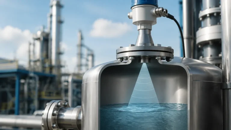
Radar Level Transmitter Chamber
Radar Level Transmitter Chamber: An Engineering Guide to Bypass Measurement Systems
In complex industrial processes, achieving a stable and accurate liquid level reading is often challenged by internal tank obstructions, surface foam, or extreme turbulence. For many engineers and procurement specialists, the integration of Radar Level Meters within a dedicated radar level transmitter chamber (also known as a bypass chamber or side-mounted bridle) provides the necessary isolation to ensure measurement reliability.
This article examines the technical principles, selection criteria, and installation requirements for using radar technology within external chambers, providing a factual framework for B2B industrial applications.
1. Measurement Principles in a Confined Space
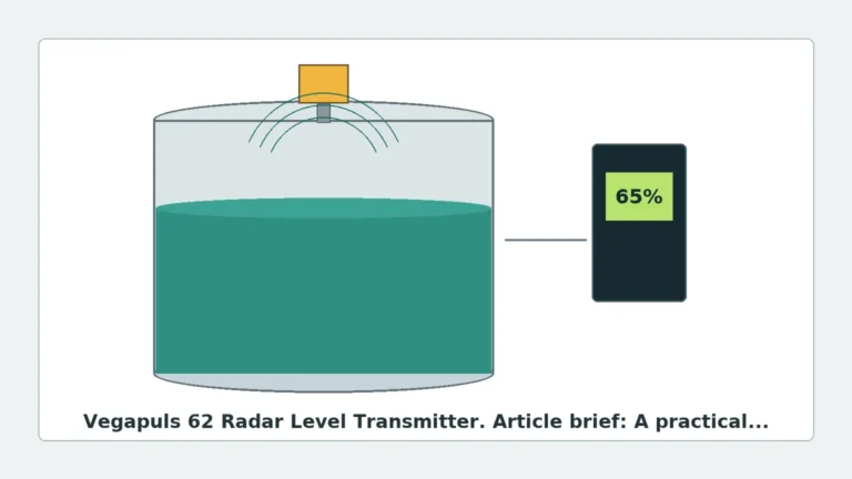
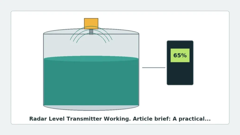
Radar level measurement relies on the Time-of-Flight (ToF) principle. The transmitter emits high-frequency electromagnetic pulses (Pulse Radar) or a continuous wave with a varying frequency (Frequency Modulated Continuous Wave – FMCW). These waves travel at the speed of light, reflect off the surface of the process medium, and return to the sensor.
The Role of the Chamber
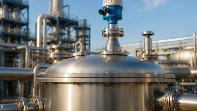
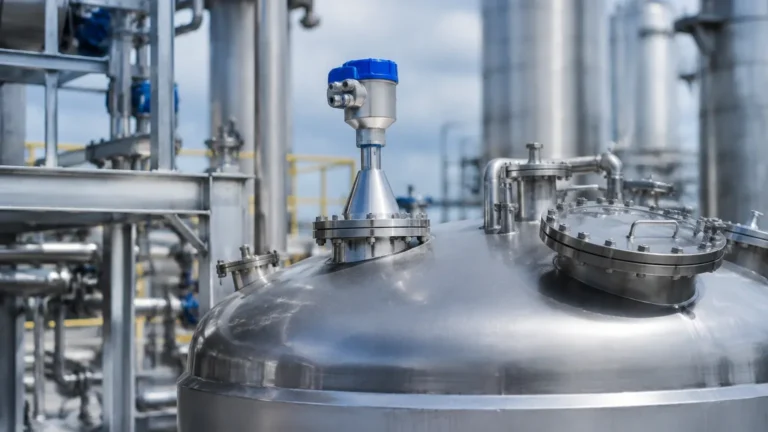
When a radar transmitter is mounted on a radar level transmitter chamber, the chamber acts as a "stilling well" isolated from the main process vessel. The liquid level in the chamber equalizes with the level in the tank through communicating pipework.
There are two primary ways the chamber interacts with the radar signal:
1. Waveguide Effect: In narrow chambers, the metallic walls guide the electromagnetic waves, minimizing signal dispersion. This is particularly effective for low dielectric constant ($ε_r$) fluids, as it concentrates the radar energy on a smaller surface area.
2. Surface Stabilization: By isolating the liquid from agitators, boiling surfaces, or inflowing product, the chamber provides a calm surface, significantly increasing the Signal-to-Noise Ratio (SNR).
2. Why Use a Radar Level Transmitter Chamber?
While non-contact radar is often preferred for its low maintenance, direct tank mounting is not always feasible. The use of a bypass chamber is recommended in the following scenarios:
* Internal Obstructions: Tanks with heating coils, baffles, or agitators can create "false echoes" that interfere with the radar signal. A chamber removes these variables from the radar’s path.
* Turbulence and Foam: Heavy foaming or splashing on the liquid surface absorbs or scatters radar pulses. The chamber provides a quiescent zone where foam is naturally suppressed.
* Maintenance Accessibility: A bypass chamber allows the instrument to be isolated via valves. This means the radar unit can be calibrated or replaced without depressurizing the main process vessel, reducing downtime in 24/7 operations.
* Interface Measurement: For liquids with distinct layers (e.g., oil and water), a chamber helps maintain a stable interface level, allowing Guided Wave Radar (GWR) or high-frequency non-contact radar to track the transition more accurately.
3. Technical Selection Criteria
Selecting the correct radar level transmitter chamber requires a detailed understanding of the process conditions and the radar frequency being utilized.
Material and Pressure Ratings
Chambers are typically manufactured from stainless steel (304/316L), though exotic alloys like Hastelloy or Monel are used for corrosive chemical applications. The pressure rating must match or exceed the vessel's design pressure, often following ASME B31.3 or EN 13480 standards.
Diameter and Frequency Compatibility
The diameter of the chamber must be compatible with the radar antenna type.
| Radar Type | Recommended Chamber Diameter (Metric) | Recommended Chamber Diameter (Imperial) |
| :— | :— | :— |
| 26 GHz Pulse Radar | 50 mm to 100 mm | 2" to 4" |
| 80 GHz FMCW Radar | 40 mm to 80 mm | 1.5" to 3" |
| Guided Wave Radar (GWR) | 50 mm to 100 mm | 2" to 4" |
Note: 80 GHz radar units have a much narrower beam angle (often as low as 3°), making them ideal for smaller diameter chambers without the risk of wall interference.
Selection Table: Process Compatibility
| Process Condition | Chamber Requirement | Radar Recommendation |
| :— | :— | :— |
| High Temperature (>200°C) | Extended neck / Heat fins | 26 GHz or GWR |
| Low Dielectric (ε_r < 1.9) | Narrow chamber (Waveguide) | GWR or 80 GHz FMCW |
| Viscous/Crystallizing | Steam jacketed chamber | Non-contact Radar |
| High Pressure (>40 Bar) | Sch 80 or higher piping | GWR with Coaxial Probe |
4. Installation Considerations and Constraints
Proper installation is critical to prevent measurement errors. Engineers must adhere to the following factual boundaries:
Verticality
The chamber must be installed perfectly vertical. A tilt of more than 1° can cause the radar signal (especially in GWR applications) to contact the chamber wall, leading to signal loss or false readings.
Venting and Draining
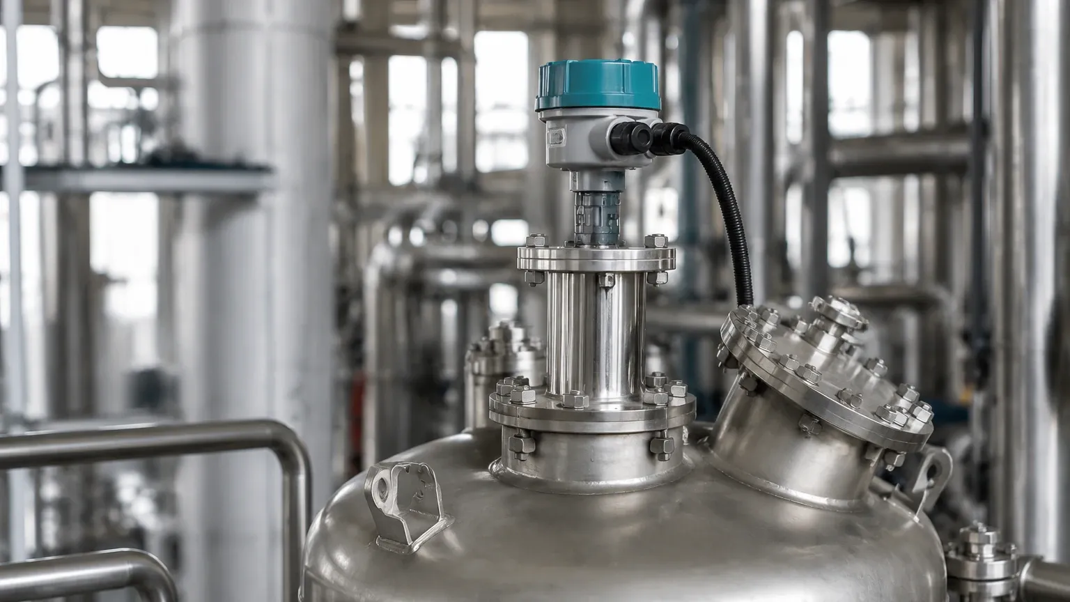
* Top Vent: A vent valve or plug is required at the highest point of the chamber to prevent air pockets that could trap liquid and cause false high readings.
* Bottom Drain: A drain valve is essential for removing sediment and for clearing the chamber during commissioning or maintenance.
Pipe Connections
The process connections (side-side or side-bottom) should be of sufficient diameter (typically DN25/1" or larger) to ensure the liquid level in the chamber responds quickly to changes in the vessel. If the liquid is viscous, larger connections are required to prevent lag.
The "Dead Zone" (Blocking Distance)
Every radar transmitter has a near-zone blocking distance (typically 50 mm to 200 mm from the flange). The chamber design must ensure that the maximum liquid level does not enter this dead zone, or the transmitter will report an error or a static high-level reading.
5. Application Risks and Limitations
While a radar level transmitter chamber solves many problems, it introduces specific risks that must be managed:
1. Build-up and Clogging: In applications with heavy paraffin, waxes, or metallic dust, the chamber can become clogged. Regular flushing via the drain port is necessary. If build-up occurs on the chamber walls, it can attenuate the signal.
2. Condensation: In high-humidity or high-temperature steam applications, condensation can form on the radar antenna. While many Radar Level Meters feature dripping-lens designs to shed water, excessive condensation in a narrow chamber can still cause signal scattering.
3. Boiling and Flashing: If the liquid in the chamber is at a different temperature than the vessel (due to lack of insulation), it may boil or flash, creating gas bubbles that interfere with the radar signal.
6. Information for International Buyers and Procurement
When sourcing a radar level transmitter chamber for global projects, international buyers should confirm the following specifications with the manufacturer:
* Code Compliance: Ensure the welding and pressure testing comply with local regulations (e.g., PED in Europe, ASME in the Americas, or GB in China).
* Surface Finish: For food or pharmaceutical applications, specify the internal Ra (Roughness Average) to prevent bacterial growth.
* NACE Compliance: For oil and gas applications involving sour gas (H2S), materials must comply with NACE MR0175/ISO 15156.
* Documentation: Request a Material Traceability Report (MTR), Hydrostatic Test Certificate, and Weld Procedure Specifications (WPS).
7. Frequently Asked Questions (FAQ)
Q: Can I use a non-contact radar in a chamber designed for a float-type level gauge?
A: Yes, provided the chamber diameter is large enough for the radar's beam angle and the internal surface is relatively smooth. You must ensure there are no internal pins or springs left over from the magnetic float system.
Q: What is the advantage of an 80 GHz radar in a bypass chamber?
A: The 80 GHz frequency allows for a much smaller antenna and a tighter beam. This minimizes reflections from the chamber walls and allows for installation in narrower pipes (down to 40 mm) without the signal interference common with lower-frequency units.
Q: Does the dielectric constant change when using a chamber?
A: No, the dielectric constant ($ε_r$) is a property of the fluid. However, the chamber concentrates the signal, which makes it easier for the radar to detect the reflection from low-$ε_r$ fluids like liquid nitrogen or hydrocarbons.
Q: How do I handle liquids that might solidify in the chamber?
A: For such applications, a steam-jacketed or electrically heat-traced chamber is required to maintain the process temperature and ensure the fluid remains in a liquid state.
Conclusion
The integration of a radar level transmitter chamber is a proven engineering solution for stabilizing level measurements in challenging industrial environments. By understanding the interaction between the radar's electromagnetic waves and the chamber's geometry, engineers can design systems that offer high accuracy, ease of maintenance, and long-term reliability. When selecting equipment, always prioritize material compatibility and pressure ratings to ensure safety and performance in the field.