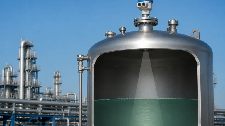
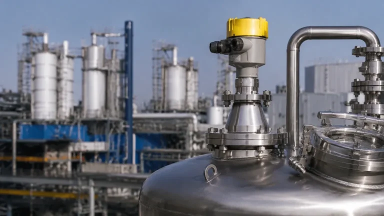
Radar Level Transmitter with Remote Display
Radar Level Transmitter with Remote Display: A Practical Engineering Guide
In modern industrial automation, the ability to monitor fluid and solid levels from a safe and accessible distance is a critical requirement for operational efficiency and personnel safety. A radar level transmitter with remote display serves as a vital bridge between the harsh environment of a process vessel and the control room or ground-level monitoring station. This configuration allows engineers to access real-time data, configure sensor parameters, and troubleshoot issues without climbing tall silos or entering hazardous zones.
Industrial level measurement often involves high temperatures, corrosive chemicals, or high-pressure environments. For these applications, Radar Level Meters have become the gold standard due to their non-contact nature and high accuracy. This guide explores the engineering principles, selection criteria, and installation best practices for radar transmitters integrated with remote display units.
Understanding Radar Measurement Principles
Before selecting a transmitter configuration, it is essential to understand how radar technology captures level data. Radar level sensors operate on the "Time of Flight" (ToF) principle, utilizing electromagnetic waves to detect the distance to a product surface.
Pulse Radar (Pulsed Time-of-Flight)
Pulse radar transmitters emit short-duration microwave pulses toward the target material. The sensor measures the time it takes for the pulse to travel to the surface and reflect back to the antenna. Since the speed of light is constant, the distance is calculated as:
*Distance = (Speed of Light × Time) / 2*
Pulse radar is generally cost-effective and suitable for simple liquid applications with relatively calm surfaces. It often operates at frequencies around 6GHz or 26GHz.
FMCW Radar (Frequency Modulated Continuous Wave)
FMCW radar is the preferred technology for complex industrial environments. Instead of pulses, the transmitter emits a continuous signal with a constantly changing frequency. The reflection from the material surface is received and compared against the emitted signal. The frequency difference between the transmitted and received signals is directly proportional to the distance.
High-frequency FMCW radar (e.g., 80GHz) offers a narrower beam angle and higher resolution, making it ideal for vessels with internal obstructions or materials with low dielectric constants. When paired with a radar level transmitter with remote display, the high-resolution data provided by FMCW technology allows for detailed echo curve analysis on the remote screen.
The Role of the Remote Display in Industrial Systems
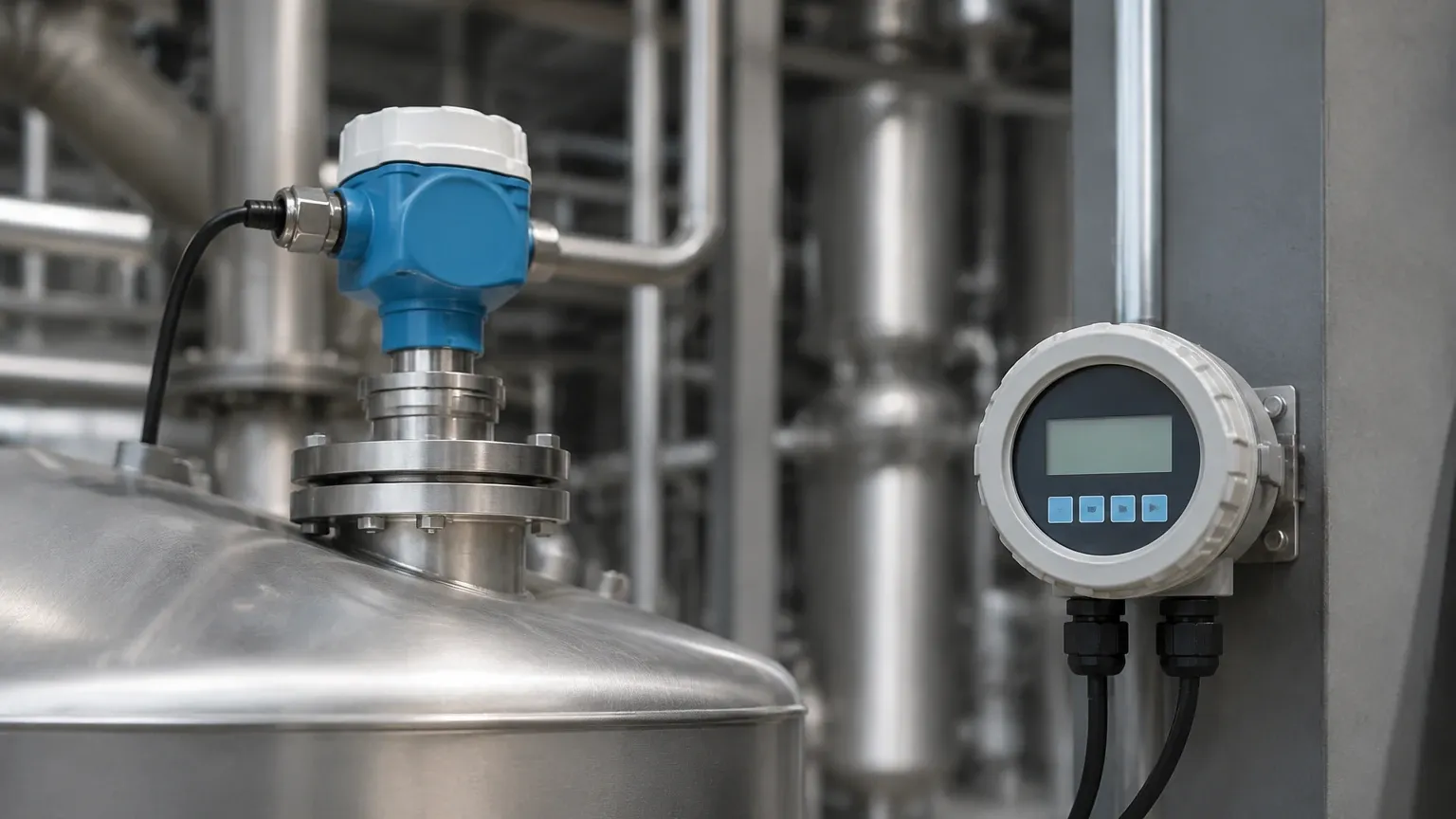
A remote display unit is more than just a secondary screen; it is a functional extension of the transmitter electronics. In many industrial setups, the radar sensor is mounted at the top of a tank that may be 20 or 30 meters (approx. 65 to 100 feet) high.
Key Functions of Remote Displays:
1. Local Visualization: Provides onsite operators with immediate access to level, volume, or mass data at eye level.
2. Parameter Configuration: Allows for full programming of the radar sensor (e.g., tank height, dielectric constant, damping) from the ground via HART, RS485, or proprietary digital protocols.
3. Signal Diagnostics: Displays the echo curve, which is critical for identifying false reflections from agitators, heating coils, or tank walls.
4. Power Distribution: In some split-architecture designs, the remote display unit acts as the power supply interface for the sensor head, simplifying wiring.
Selection Criteria for Radar Transmitters with Remote Displays
Choosing the right system requires a thorough analysis of the process media and the physical environment. The following table provides a comparison of common radar configurations used in conjunction with remote displays.
Selection Table: Radar Technology Comparison
| Feature | 26GHz Pulse Radar | 80GHz FMCW Radar | Guided Wave Radar (GWR) |
| :— | :— | :— | :— |
| Best Application | Large tanks, simple liquids | Small vessels, solids, turbulent surfaces | Low dielectric liquids, interface measurement |
| Beam Angle | 8° to 20° (Wide) | 3° to 8° (Narrow) | N/A (Follows probe) |
| Accuracy | ±3 mm to ±5 mm | ±1 mm to ±2 mm | ±2 mm |
| Measuring Range | Up to 30m (98 ft) | Up to 120m (393 ft) | Up to 30m (98 ft) |
| Remote Display Compatibility | Standard 4-20mA/HART | High-speed RS485/Modbus | 4-20mA/HART |
| Sensitivity to Obstacles | High | Low | Moderate |
Process Media Considerations
* Dielectric Constant ($ε_r$): Materials with low dielectric constants (like oils or plastic pellets) reflect less energy. High-frequency FMCW radar is typically required for these media to ensure the remote display receives a stable signal.
* Vapor and Dust: If the process generates heavy steam or dust, a radar transmitter with a higher frequency and specialized lens antenna is necessary to penetrate the atmosphere and maintain measurement integrity.
Installation and Wiring Considerations
The reliability of a radar level transmitter with remote display depends heavily on correct installation. Unlike integrated units, split-system installations involve additional wiring and signal integrity concerns.
1. Mounting Location
* Avoid the Center: Never mount the radar sensor in the exact center of a dome-roof tank, as this can cause multiple reflections that confuse the sensor.
* Distance from Walls: Maintain a minimum distance from the tank wall (typically 1/10th of the tank height) to prevent interference.
* Nozzle Geometry: Ensure the antenna extends slightly beyond the mounting nozzle to prevent signal ringing within the pipe.
2. Wiring for Remote Displays
* Cable Shielding: Use twisted-pair shielded cables to protect the signal from electromagnetic interference (EMI) caused by nearby motors or high-voltage lines.
* Distance Limits: For 4-20mA signals, distances up to 1,000 meters (approx. 3,280 feet) are possible, but voltage drop must be calculated. For digital RS485 communication, signal repeaters may be required for very long runs.
* Hazardous Areas: If the sensor is in an explosive atmosphere (ATEX/IECEx Zone 0 or 1), the remote display must be either intrinsically safe or located in a safe area behind a galvanic isolator/barrier.
Limitations and Application Risks
While radar technology is robust, engineers must be aware of specific limitations that can affect the data shown on the remote display:
* Heavy Foam: Extremely dense, thick foam can absorb radar signals entirely, leading to a "loss of echo." In such cases, guided wave radar or hydrostatic transmitters might be more appropriate.
* Internal Obstructions: Agitators, ladders, and spray balls create false echoes. While modern radar software can "map out" these reflections, the initial setup requires careful configuration via the remote display interface.
* Minimum Dielectric Constant: Most non-contact radars struggle with materials having an $ε_r < 1.4$. If the remote display shows an unstable reading, it may be due to the signal passing through the material and reflecting off the tank bottom instead of the surface.
Maintenance and Troubleshooting
The primary advantage of the remote display is simplified maintenance. Regular checks should include:
1. Echo Curve Verification: Periodically check the echo curve on the remote display to ensure the "signal-to-noise" ratio remains healthy. A degrading signal may indicate buildup on the antenna.
2. Antenna Cleaning: In sticky or crystallizing applications, the radar antenna may require cleaning. Some transmitters feature an air purge connection to prevent buildup automatically.
3. Loop Testing: Use the remote display to force a 4-20mA output (e.g., 4mA, 12mA, 20mA) to verify that the PLC or SCADA system is receiving the correct scaled values.
Frequently Asked Questions (FAQ)
Q: Can I use a remote display from a different manufacturer than the radar transmitter?
A: If the transmitter uses a standard 4-20mA or HART protocol, a universal industrial indicator can display the level. However, to access full configuration menus and echo curves, the display and transmitter usually need to be from the same manufacturer or support a standardized DTM/EDDL interface.
Q: How does temperature affect the remote display reading?
A: Radar waves are largely unaffected by air temperature. However, the electronics in the remote display unit have operating limits (typically -20°C to +60°C). If the display is installed outdoors in extreme climates, a heated or cooled enclosure may be necessary.
Q: What is the benefit of an 80GHz radar for a remote display setup?
A: The 80GHz frequency allows for a much smaller antenna and a tighter beam. This means less interference from tank walls and internal structures, resulting in a "cleaner" data stream for the remote display and more accurate control.
Conclusion
Implementing a radar level transmitter with remote display is a strategic choice for industrial facilities prioritizing safety and precision. By separating the sensing element from the user interface, companies can ensure that critical level data is always accessible, even in the most challenging process environments. When selecting a system, engineers should prioritize frequency (such as 26GHz or 80GHz) based on the material properties and vessel geometry, while ensuring that the remote display provides the diagnostic depth required for long-term maintenance. For high-quality instrumentation tailored to these needs, exploring professional Radar Level Meters is the first step toward a reliable level measurement solution.
Download Radar Level Transmitter with Remote Display as a PDF