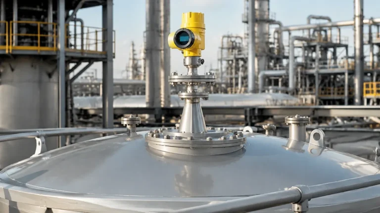
Radar Type Level Transmitter Nozzle Size
Radar Type Level Transmitter Nozzle Size: A Technical Engineering Guide
In industrial process automation, the accuracy of non-contact level measurement is heavily dependent on the physical installation environment. Among the various factors influencing performance, the radar type level transmitter nozzle size and geometry are perhaps the most critical. A poorly designed or incorrectly sized mounting nozzle can introduce signal interference, create significant "dead zones," and lead to unreliable data in critical applications such as chemical storage, water treatment, and oil and gas processing.
This guide provides a comprehensive technical analysis of nozzle selection for Radar Level Meters, detailing measurement principles, installation constraints, and practical selection criteria for B2B procurement and engineering design.
Understanding Radar Measurement Principles
Before determining the appropriate nozzle size, it is essential to understand how radar signals interact with the mounting structure. Radar level transmitters operate on the Time of Flight (ToF) principle, utilizing either Pulse Radar or Frequency Modulated Continuous Wave (FMCW) technology.
The Beam Angle and Signal Spread
Radar waves are emitted from the antenna in a conical shape. The concentration of this energy is defined by the "beam angle," which is typically measured at the point where the power density is half of its maximum value (-3dB).
* High-Frequency Radar (e.g., 80GHz): These units typically offer very narrow beam angles (as low as 3° to 6°). This allows for installation in smaller nozzles and closer to tank walls.
* Mid-Frequency Radar (e.g., 26GHz): These units have wider beam angles (typically 8° to 20°), requiring larger nozzles or shorter nozzle heights to prevent the signal from hitting the nozzle interior.
The Impact of Nozzle Interference
When a radar signal is emitted, any physical obstruction within the beam's path reflects energy back to the sensor. If the radar type level transmitter nozzle size is too narrow or the nozzle is too long, the radar waves will strike the inner wall of the nozzle. This creates "ringing" or high-amplitude false echoes near the top of the tank, effectively increasing the "blind zone" (dead band) where the sensor cannot accurately measure the liquid level.
The Relationship Between Nozzle Diameter and Height
The primary rule in radar installation is the ratio between the nozzle diameter ($D$) and the nozzle height ($L$). Ideally, the radar antenna should extend beyond the bottom of the nozzle to allow the signal to spread freely into the tank. However, in many pressurized or insulated vessels, the antenna must remain recessed within the nozzle.
1. Horn Antennas (Standard)
For traditional horn antennas, the diameter of the nozzle must be larger than the diameter of the horn. More importantly, the horn should ideally protrude at least 10mm (0.4") below the nozzle end. If the horn is recessed, the nozzle walls must be smooth and free of burrs, welds, or transitions that could cause reflections.
2. Lens Antennas (Flush Mount)
Modern high-frequency Radar Level Meters often use lens antennas. These are designed to be flush with the process connection. For these models, the nozzle height is less restrictive because the beam is highly focused, but the nozzle diameter must still match the sensor's process connection (e.g., DN50, DN80, or DN100) to avoid edge reflections.
3. Rod Antennas
Rod antennas are often used in corrosive environments or small vessels. Because the signal is emitted along the length of the rod, the nozzle diameter must be significantly wider than the rod to prevent the "near-field" effect from drowning out the return signal from the product surface.
Practical Selection Table for Nozzle Sizing
The following table provides general engineering recommendations for nozzle dimensions based on common radar frequencies and antenna types.
| Radar Frequency | Antenna Type | Min. Nozzle Diameter (D) | Max. Recommended Nozzle Height (L) | Typical Beam Angle |
| :— | :— | :— | :— | :— |
| 80 GHz | Lens / Flush | DN50 (2") | 200 mm (8") | 6° |
| 80 GHz | Lens / Flush | DN80 (3") | 300 mm (12") | 3° |
| 26 GHz | Horn | DN80 (3") | Horn must protrude | 12° |
| 26 GHz | Horn | DN100 (4") | 150 mm (6") if recessed | 8° |
| 6 GHz | Horn | DN150 (6") | 200 mm (8") | 23° |
| Rod Type | PTFE Rod | DN50 (2") | 100 mm (4") | 20° |
*Note: Always refer to the specific manufacturer's datasheet, as Welk instruments may utilize optimized signal processing to handle longer nozzles than standard industry averages.*
Critical Installation Considerations
When specifying the radar type level transmitter nozzle size, engineers must account for the following physical constraints:
Nozzle Interior Finish
The interior of the mounting nozzle should be as smooth as possible. Internal weld seams are a common source of false echoes. If a nozzle is fabricated from pipe sections, the internal welds should be ground flush. For high-accuracy applications, seamless tubing is preferred over standard welded pipe for the nozzle construction.
Obstructions Near the Nozzle
The nozzle should not be placed directly above internal tank structures such as heating coils, ladders, or agitators. Even if the nozzle size is correct, if the resulting beam path intersects with a stationary object, the radar will lock onto the obstruction instead of the liquid surface.
Positioning on the Tank
* Avoid the Center: Do not install the nozzle in the center of a domed or flat-roof tank. This can lead to multiple reflections (parabolic effect) that amplify noise.
* Distance from Wall: The nozzle should be placed at a distance from the tank wall of approximately 1/4 to 1/6 of the tank diameter. However, ensure the beam angle does not hit the wall at the lowest measurement point.
Use of Ball Valves and Isolation
If the radar is mounted on a ball valve for maintenance isolation, the valve must be "full bore." Any reduction in the internal diameter through the valve body will act as a secondary nozzle, potentially causing signal interference. The combined height of the nozzle and the valve must be calculated as the total "L" dimension when checking against the beam angle.

Application Risks and Limitations
Even with the correct radar type level transmitter nozzle size, certain process conditions can affect performance:
1. Condensation and Buildup: In applications with heavy vapors (e.g., hot water or chemicals), moisture can collect on the antenna or the inner rim of the nozzle. If the nozzle is too narrow, this buildup can bridge the gap between the antenna and the nozzle wall, causing a short-circuit of the microwave signal (a "high-level" false alarm).
2. Manways and Large Openings: While it might seem beneficial to mount a radar on a large manway cover to avoid nozzle constraints, the large flat surface of the cover can sometimes create secondary reflections. A dedicated nozzle of the correct size is always preferable.
3. Nozzle Inclination: The nozzle must be installed perfectly vertical (perpendicular to the liquid surface). An inclination of even 1-2 degrees can significantly reduce the strength of the return signal, especially on liquid surfaces with low dielectric constants.
Buyer’s Checklist: Confirming Specifications
For international buyers and procurement managers, confirming the following details with the supplier will ensure the Radar Level Meters perform as expected:
* What is the exact internal diameter (ID) of the existing nozzle? (Standard pipe schedules like Sch 40 vs. Sch 80 have different IDs).
* What is the total height from the flange face to the tank interior?
* What is the dielectric constant (Dk) of the medium? (Low Dk materials like oils require a cleaner signal path than high Dk materials like water).
* Does the radar include "False Echo Suppression" software? This allows the transmitter to "learn" the reflections caused by the nozzle and ignore them during operation.
Frequently Asked Questions (FAQ)
Q: Can I install a radar in a nozzle that is longer than the recommended limit?
A: Yes, but you may need to use a wave guide (still pipe) or a radar with a higher frequency (80GHz) and a specialized antenna extension. Alternatively, signal processing can sometimes "map out" the nozzle reflections, but this may increase the minimum measurable distance (dead zone).
Q: How does nozzle size affect measurement in solids?
A: For bulk solids, the material surface is often angled (repose angle). A larger nozzle or a swivelling flange (aiming flange) is often required to ensure the radar beam is directed at the material correctly and to prevent the nozzle from clipping the signal.
Q: Is it better to have a nozzle that is too large or too small?
A: Generally, a larger nozzle is safer as it reduces the risk of the beam hitting the sidewalls. However, a nozzle that is significantly larger than the antenna requires a larger process flange, which increases cost and weight.
Conclusion
Selecting the correct radar type level transmitter nozzle size is a balance between mechanical constraints and electronic requirements. By adhering to the $L:D$ ratio guidelines and choosing the appropriate frequency for the nozzle geometry, engineers can ensure high-precision level measurement with minimal maintenance. For modern industrial applications, the shift toward 80GHz technology has greatly simplified nozzle selection, allowing for more compact and versatile installations across the process industries.