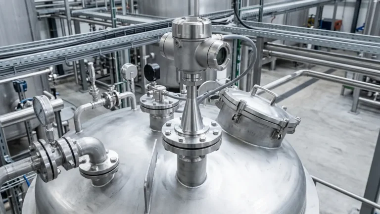
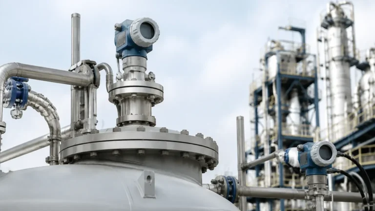
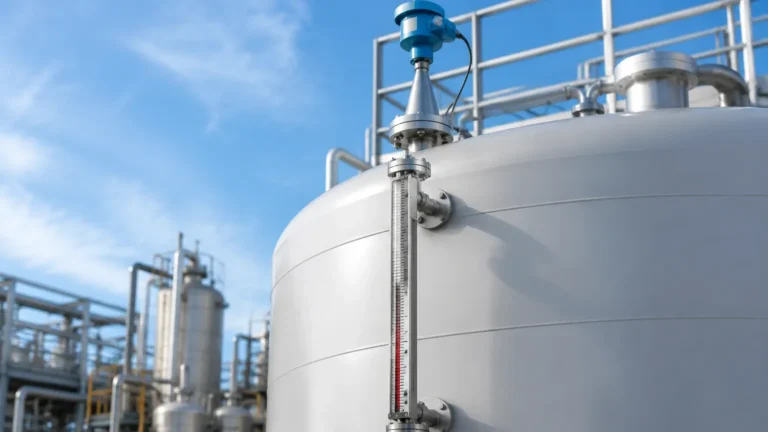
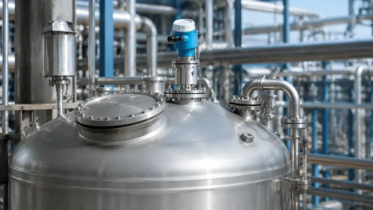
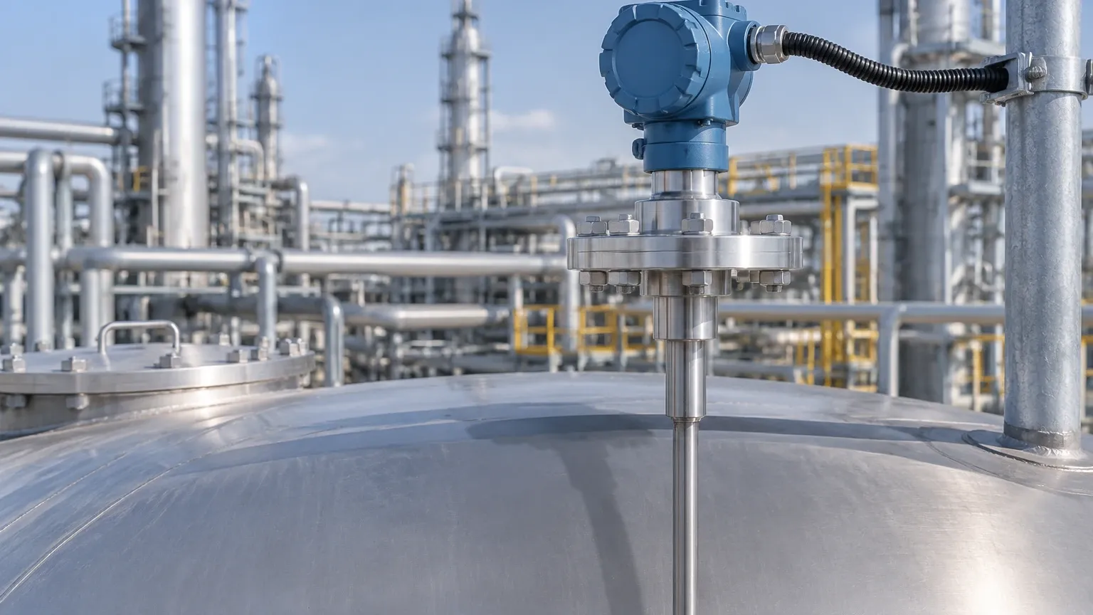
Rosemount Guided Wave Radar Level Transmitter
Rosemount Guided Wave Radar Level Transmitter: A Technical Engineering Guide
In the landscape of industrial automation, accurate level measurement is a critical requirement for process safety, inventory management, and operational efficiency. Among the various technologies available, the rosemount guided wave radar level transmitter has established itself as a versatile and reliable solution for challenging environments. This article provides a comprehensive technical overview of Guided Wave Radar (GWR) technology, its operating principles, selection criteria, and practical installation considerations for engineering professionals.
Understanding the Principles of Guided Wave Radar
Guided Wave Radar technology is based on the principle of Time Domain Reflectometry (TDR). Unlike non-contact Radar Level Meters that transmit electromagnetic pulses through the air, GWR systems utilize a physical probe—often referred to as a waveguide—to direct the signal from the transmitter head to the process medium.
The Measurement Cycle
1. Pulse Emission: The transmitter electronics generate low-power, high-frequency microwave pulses (typically in the GHz range).
2. Propagation: These pulses travel down the probe at the speed of light.
3. Reflection: When the pulse encounters a change in the dielectric constant (εr) of the surrounding medium—such as the transition from air or vapor to a liquid or solid—a portion of the pulse energy is reflected back up the probe.
4. Signal Processing: The transmitter measures the time-of-flight (the interval between pulse emission and the return of the echo). Since the speed of light is constant, the distance to the surface is calculated as:
*Distance = (Speed of Light × Time of Flight) / 2*
The Role of the Dielectric Constant
The dielectric constant of the material being measured is the most significant factor in signal reflection. Materials with high dielectric constants, such as water (εr ≈ 80), produce very strong reflections. Conversely, hydrocarbon-based liquids like oil or solvents (εr ≈ 1.9 to 4.0) reflect less energy. A minimum dielectric constant is usually required for the transmitter to distinguish the surface echo from background noise, typically around εr ≥ 1.4 for most industrial GWR probes.
Comparison of Probe Types
Selecting the correct probe geometry is essential for the performance of a rosemount guided wave radar level transmitter. The choice depends on the fluid properties, the presence of internal tank obstructions, and the required measurement range.
| Probe Type | Best Use Case | Advantages | Limitations |
| :— | :— | :— | :— |
| Coaxial | Low dielectric liquids, high-pressure/temp steam | Highest signal-to-noise ratio; immune to nozzle interference | Susceptible to clogging/bridging in viscous or coating fluids |
| Twin Lead (Flexible or Rigid) | Long-range measurements in large tanks | Better signal strength than single lead; handles turbulence well | Requires spacing from tank walls and obstructions |
| Single Lead (Flexible or Rigid) | Viscous liquids, slurries, and solids | Resists coating and buildup; easiest to clean | Most sensitive to nozzle interference and nearby metal objects |
Interface Measurement Capabilities
One of the distinct advantages of GWR technology over non-contact Radar Level Meters is its ability to measure both the total level and the interface level between two immiscible liquids (e.g., oil over water).
In an interface application, the microwave pulse passes through the upper, low-dielectric layer (the "upper medium") with minimal reflection. When it hits the interface of the lower, high-dielectric layer (the "lower medium"), a second reflection is generated. This allows the transmitter to report the position of both the top surface and the interface simultaneously. For successful interface measurement, the upper medium must have a lower dielectric constant than the lower medium, and the upper layer must be at least 100 mm (4 inches) thick to allow the transmitter to resolve the two distinct echoes.
Engineering Selection Criteria
When specifying a rosemount guided wave radar level transmitter for a project, engineers must evaluate several environmental and process variables:
1. Process Temperature and Pressure
Standard GWR units typically handle temperatures up to 150°C and pressures up to 40 bar. However, high-temperature/high-pressure (HTHP) variants are available that utilize specialized ceramic-to-metal seals to withstand temperatures up to 400°C and pressures exceeding 300 bar. It is vital to confirm the seal material's compatibility with the process fluid.
2. Vapor Space Composition
Unlike ultrasonic sensors, GWR is largely unaffected by vapor, dust, or pressure changes. However, high-pressure saturated steam can slow down the microwave pulse, leading to measurement errors. In these cases, a transmitter with "Dynamic Vapor Compensation" (using a reference reflector on the probe) is necessary to maintain accuracy.
3. Probe Length and Mounting
Probes can range from 1 meter to over 50 meters (using flexible cables). The mounting nozzle height and diameter must be considered; if the nozzle is too narrow or too long, it may create parasitic reflections that interfere with the surface signal, especially with single-lead probes.
Installation Considerations and Constraints
Proper installation is the most critical factor in ensuring long-term reliability. Engineers should adhere to the following guidelines:
* The Upper Dead Zone: There is a region at the very top of the probe (near the process connection) where measurements are not possible or are less accurate. This is known as the Upper Transition Zone. Ensure the maximum liquid level does not enter this zone.
* The Lower Dead Zone: Similarly, at the end of the probe, the signal can be affected by the probe's tip or the tank bottom. A "weight" is often used on cable probes to keep them taut; the level cannot be measured accurately below the top of this weight.
* Obstruction Clearance: For single and twin-lead probes, a minimum clearance from metallic objects (ladders, agitators, or pipes) must be maintained. As a rule of thumb, maintain a 300 mm (12 inch) radius of clearance for single-lead probes.
* Nozzle Geometry: The probe should be centered within the nozzle. If using a single-lead probe in a tall nozzle, the nozzle diameter should be at least 100 mm (4 inches) to minimize signal interference.
Limitations and Application Risks
While highly robust, GWR technology is not a universal solution. Engineers must be aware of the following risks:
1. Coating and Bridging: While single-lead probes handle viscous fluids better than others, extreme buildup that bridges the gap between a twin-lead or coaxial probe and its housing will cause false high-level readings.
2. Turbulence and Foam: Heavy, dense foam can absorb the radar signal, leading to signal loss. While GWR is more resistant to foam than non-contact radar, very thick foam may still pose a challenge.
3. Probe Movement: In tanks with high-speed agitators or heavy turbulence, flexible cable probes may swing and touch the tank wall or internal structures, causing false echoes or mechanical damage. In these scenarios, the probe should be anchored or housed in a stilling well or bypass chamber.
International Buyer’s Checklist
For procurement professionals and engineers sourcing equipment for global projects, confirming the following technical details with the supplier is essential:
* Material Traceability: Request Mill Test Reports (MTRs) for wetted parts, especially for 316L Stainless Steel, Hastelloy, or Monel probes.
* Certifications: Ensure the device carries the necessary hazardous area certifications (ATEX, IECEx, or FM) and safety integrity levels (SIL 2/3) required by the site.
* Process Connection Standards: Confirm whether the flange or thread follows ASME, EN/DIN, or JIS standards to avoid mounting mismatches.
* Configuration Tools: Verify if the unit requires proprietary software or if it can be configured via standard HART, FOUNDATION Fieldbus, or PROFIBUS protocols.
Frequently Asked Questions (FAQ)
Q: Can a GWR transmitter be used in a plastic tank?
A: Yes, but since GWR relies on a ground plane for signal stability, a single-lead probe in a plastic tank may require a metal launch plate or a flange at the process connection to function correctly. Coaxial probes are the preferred choice for non-metallic tanks as they carry their own ground.
Q: How does GWR compare to non-contact radar for solids measurement?
A: GWR is excellent for powders and granules with low dielectric constants. However, the physical probe is subject to significant pull-down forces as the solids settle or are discharged. The tank roof and the probe itself must be engineered to withstand these mechanical loads.
Q: Is it possible to cut the probe to length on-site?
A: Most rosemount guided wave radar level transmitter probes (especially cable and rigid single-lead types) can be shortened in the field. However, the transmitter electronics must be reconfigured with the new probe length to maintain accuracy.
Q: Does the fluid density affect the measurement?
A: No. Unlike hydrostatic pressure transmitters, GWR measures the distance to the surface based on electromagnetic properties, making it independent of changes in fluid density or temperature-induced volume expansion.
Conclusion
The rosemount guided wave radar level transmitter represents a sophisticated intersection of microwave physics and industrial engineering. By understanding the interaction between the probe geometry and the dielectric properties of the process medium, engineers can specify a solution that provides high-precision measurement even in the presence of vapor, turbulence, or varying pressures. When compared to traditional Radar Level Meters, GWR offers superior performance in interface applications and low-dielectric environments, provided that installation constraints and probe selection are addressed during the design phase.
Download Rosemount Guided Wave Radar Level Transmitter as a PDF