Rosemount Radar Level Transmitter 5400 Manual
Rosemount Radar Level Transmitter 5400 Manual: Engineering Guide and Application Insights
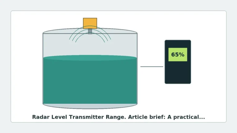
In the field of industrial process automation, non-contacting radar technology has become the benchmark for reliable liquid and slurry level measurement. The Rosemount 5400 series represents a significant segment of this market, utilizing high-frequency microwave signals to determine the distance to a product surface. For engineers and procurement specialists, understanding the technical nuances often found in a rosemount radar level transmitter 5400 manual is essential for ensuring long-term operational stability and accuracy.
This guide serves as a practical engineering reference, detailing the measurement principles, selection criteria, and installation constraints associated with high-performance Radar Level Meters. Whether you are commissioning a new unit or troubleshooting an existing installation, the following technical breakdown provides the necessary context for industrial level instrumentation.
1. Understanding the Measurement Principle
Before diving into the specifics of the hardware, it is critical to understand how the 5400 series operates. Unlike simple pulsed radar systems, the Rosemount 5400 typically employs Frequency Modulated Continuous Wave (FMCW) technology.
Frequency Modulated Continuous Wave (FMCW)
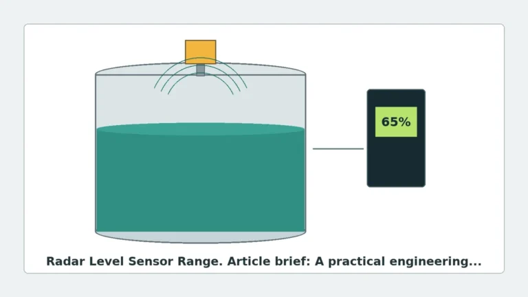
In an FMCW system, the transmitter emits a continuous electromagnetic signal with a linear frequency sweep. The signal reflects off the material surface and is received by the antenna. Because the transmitter is constantly changing the frequency of the emitted signal, there is a frequency difference between the transmitted signal and the reflected signal received at any given moment.
This frequency shift (Δf) is directly proportional to the time of flight, and therefore the distance. The primary advantage of FMCW over standard pulse radar is its ability to provide a much higher signal-to-noise ratio, which is vital when measuring materials with low dielectric constants or in turbulent conditions.
Microwave Propagation and Dielectrics
The accuracy of any radar level meter is influenced by the dielectric constant (εr) of the medium. Materials with high dielectric constants, such as water (εr ≈ 80), reflect signals strongly. Hydrocarbons and oils (εr ≈ 2-3) reflect much less energy. The 5400 series is designed with advanced signal processing to extract meaningful data even from weak reflections, a feature often detailed in the "Sensitivity" section of the technical manual.
2. Selection Criteria for Radar Level Transmitters
Selecting the correct configuration for a radar transmitter involves more than just choosing a model number. Engineers must match the antenna type and frequency to the specific process environment.
Antenna Types and Applications
| Antenna Type | Best For | Temperature/Pressure Limits | Key Advantage |
| :— | :— | :— | :— |
| Cone (Horn) Antenna | General purpose, large tanks | Up to 250°C / 40 bar | Versatile, easy to clean |
| Process Seal Antenna | Corrosive chemicals, hygienic | Up to 200°C / 25 bar | No metal parts exposed to process |
| Parabolic Antenna | Long ranges, low dielectric solids | Up to 200°C / 3 bar | Extremely focused beam |
| Extended Cone | Thick-walled or insulated nozzles | Matches Cone specs | Prevents signal interference in nozzles |
| Waveguide | Small tanks, bypass pipes | Process dependent | Eliminates beam spread issues |
Frequency Considerations
The Rosemount 5400 series typically operates in the 6 GHz (C-band) or 26 GHz (K-band) range.
* Low Frequency (6 GHz): Better for applications with heavy foam, steam, or dust, as the longer wavelength can penetrate these obstacles more effectively.
* High Frequency (26 GHz): Offers a narrower beam angle, which is ideal for avoiding internal tank obstructions like agitators or ladders, and allows for smaller antenna sizes.
3. Installation Guidelines and Constraints
A common cause of failure in radar level measurement is improper installation. Following the rosemount radar level transmitter 5400 manual specifications regarding placement is mandatory for achieving the rated accuracy of ±3 mm (0.1 in.).
Nozzle Geometry
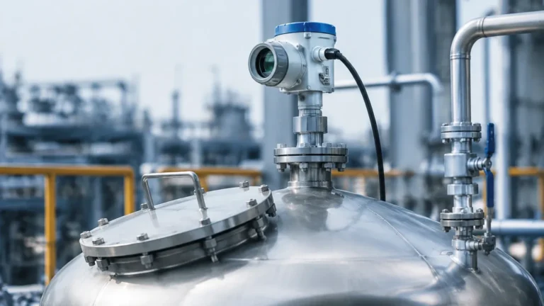
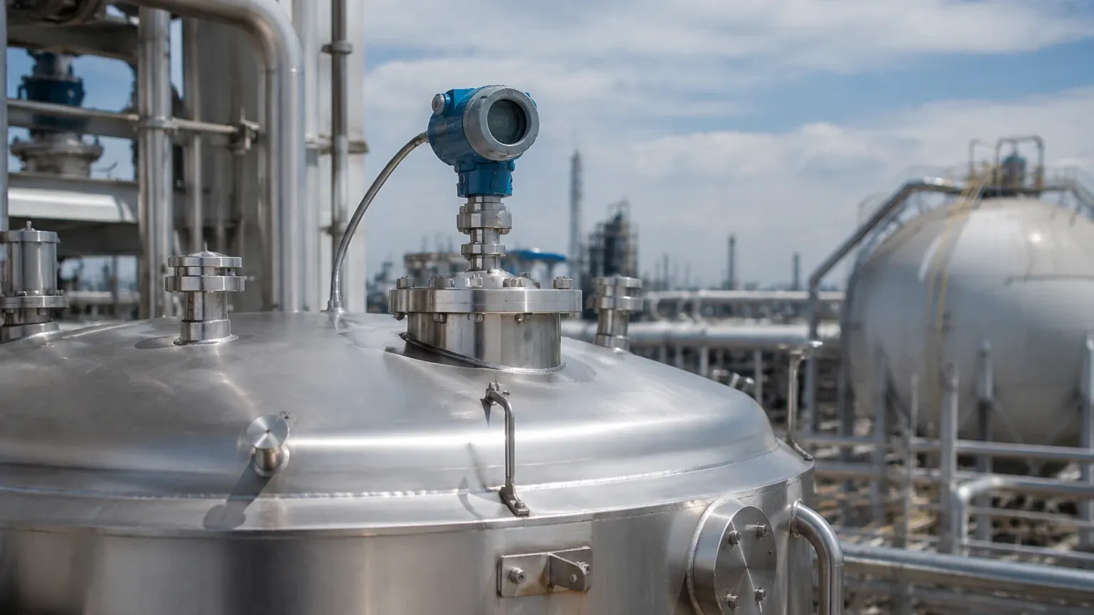
The nozzle on which the transmitter is mounted should be as short as possible. If the nozzle is too long or has internal welds, it can create "ringing" or parasitic reflections that mask the actual level signal. Ideally, the antenna should extend slightly below the nozzle bottom into the tank space.
Mounting Position
* The 1/6 Diameter Rule: For vertical cylindrical tanks, the transmitter should ideally be placed at 1/6 of the tank diameter from the side wall.
* Avoid the Center: Never mount the radar in the exact center of a domed tank, as this can cause multiple reflections to converge, creating a false high-signal peak.
* Clearance: Ensure the signal beam (typically a 10° to 20° cone) does not intersect with the filling stream, agitator blades, or heating coils.
Alignment
For liquid applications, the transmitter must be mounted perfectly vertical. Even a few degrees of tilt can cause the signal to reflect away from the antenna rather than back to it, significantly reducing the signal strength.
4. Configuration and Software Integration
Modern Radar Level Meters are rarely configured via local buttons alone. The Rosemount 5400 utilizes EDDL (Electronic Device Description Language) and DTM (Device Type Manager) technologies to integrate with host systems.
Rosemount Radar Master
This is the proprietary software used to configure the 5400. It allows engineers to view the "Echo Curve." Analyzing the echo curve is the most effective way to troubleshoot. It shows the amplitude of all reflections versus distance. By using "False Echo Suppression," an engineer can tell the transmitter to ignore static reflections from a fixed internal pipe or bracket.
Wiring and Power
The 5400 is a 2-wire, loop-powered device (4-20 mA with HART). It typically requires a minimum of 16V DC at the transmitter terminals when the loop current is 22.5 mA. Using shielded twisted pair cabling is essential to prevent EMI (Electromagnetic Interference) from variable frequency drives (VFDs) or other heavy industrial equipment.
5. Application Risks and Limitations
While radar is highly robust, it is not a "one size fits all" solution. Buyers and engineers should be aware of the following limitations:
1. Heavy Foam: While some radar frequencies can penetrate light foam, extremely dense, thick foam (like shaving cream) can absorb the microwave signal entirely, leading to a "Loss of Echo" (LOE) error.
2. Vacuum Conditions: Microwave signals do not require a medium to travel, so they work perfectly in a vacuum. However, the mechanical seals and gaskets must be rated for vacuum service to prevent air ingress.
3. Extremely Low Dielectrics: Materials with εr < 1.4 (such as liquid nitrogen or some liquefied gases) may require a Guided Wave Radar (GWR) rather than a non-contacting radar to ensure a reliable reflection.
4. Condensation: Heavy condensation on the antenna lens can attenuate the signal. In these cases, choosing an antenna with a PTFE drip-off shield or a parabolic antenna with a purging connection is recommended.
6. Maintenance and Troubleshooting
According to the rosemount radar level transmitter 5400 manual, these units are virtually maintenance-free because they have no moving parts. However, periodic verification is recommended.
* Signal Quality Metrics: Monitor the "Signal Strength" and "Surface Confidence" parameters. A gradual drop in signal strength over months may indicate buildup on the antenna.
* Cleaning: If the process involves crystallizing or sticky media, the antenna may require periodic cleaning. Use a soft cloth and a solvent compatible with the antenna material (usually 316L Stainless Steel or PTFE).
* Error Codes: Common HART error codes include "Low Detector Voltage" (check power supply) and "Electronic Hardware Error" (requires factory service).
7. Frequently Asked Questions (FAQ)
Q: Can the Rosemount 5400 be used for solids level measurement?
A: While primarily designed for liquids, it can be used for solids if the material has a relatively flat surface and a sufficient dielectric constant. For dusty grain silos, a dedicated solids radar with a higher power output and a dust-purging system is usually preferred.
Q: What is the difference between the Rosemount 5402 and 5408?
A: The 5402 is part of the legacy 5400 series (FMCW). The 5408 is the newer generation designed for simplified use and improved safety (SIL 2/3 capable). The 5408 uses a different software interface but follows similar installation physics.
Q: How do I perform a proof test for SIL applications?
A: The manual specifies a procedure involving a partial stroke test or a full-level cycle. This ensures the 4-20 mA output correctly tracks the level across the entire calibrated range and that the alarm states are functional.
Q: Does the transmitter require recalibration if the fluid density changes?
A: No. One of the greatest advantages of radar technology is that it measures distance based on the speed of light. Unlike hydrostatic pressure transmitters, radar is unaffected by changes in density, pressure, or temperature.
Conclusion
The Rosemount 5400 Radar Level Transmitter remains a workhorse in industries ranging from oil and gas to water treatment. By adhering to the engineering principles of FMCW signal processing and following the strict installation guidelines regarding nozzle placement and beam clearance, users can achieve exceptional measurement reliability. For those seeking alternative high-precision solutions, exploring the wider range of Radar Level Meters can provide cost-effective options tailored to specific industrial requirements. Always consult the specific version of your device's manual for wiring diagrams and safety certifications relevant to your region.
Download Rosemount Radar Level Transmitter 5400 Manual as a PDF