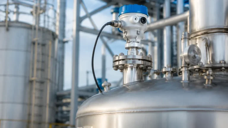
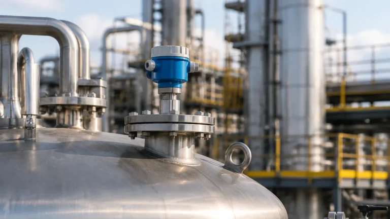
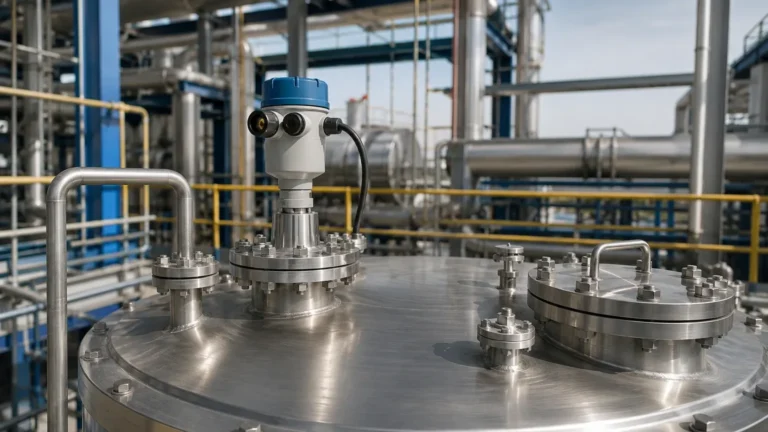
Emerson Radar Level Transmitter 5301
Emerson Radar Level Transmitter 5301: Engineering Guide to Guided Wave Radar Technology
In the field of industrial process automation, achieving precise level measurement in challenging environments is critical for operational safety and efficiency. Among the various technologies available, Radar Level Meters have become the industry standard for high-accuracy liquid and solid level detection. Specifically, the Emerson Rosemount 5301 series represents a sophisticated implementation of Guided Wave Radar (GWR) technology, designed to handle complex process conditions that often defeat traditional measurement methods.
This guide explores the technical principles, selection criteria, and installation requirements for the Emerson radar level transmitter 5301, providing engineers and procurement professionals with the factual data needed to integrate these instruments into industrial workflows.
1. Understanding the Measurement Principle: Guided Wave Radar (GWR)
Before selecting a specific transmitter, it is essential to understand how Guided Wave Radar functions. Unlike non-contact radar, which broadcasts electromagnetic waves through the air, GWR utilizes a physical probe to guide low-energy microwave pulses from the transmitter head to the process media.
Time Domain Reflectometry (TDR)
The Emerson 5301 operates on the principle of Time Domain Reflectometry (TDR). The transmitter emits a series of microwave pulses that travel down the probe. When these pulses reach the surface of the medium (liquid or solid), a portion of the energy is reflected back to the transmitter due to the change in the dielectric constant ($ε_r$) between the vapor space and the product.
By measuring the time-of-flight—the interval between the pulse emission and the reception of the echo—the device calculates the distance to the surface. Since the speed of light is constant, the distance is determined by the formula:
$$Distance = \frac{Speed\ of\ Light \times Time-of-Flight}{2}$$
The Role of the Dielectric Constant
The dielectric constant of the material is the primary factor determining the strength of the reflected signal. Materials with high dielectric constants, such as water ($ε_r ≈ 80$), produce very strong reflections. Conversely, hydrocarbons and oils often have low dielectric constants ($ε_r < 2$), which result in weaker reflections. The Emerson 5301 is engineered with high-sensitivity electronics and "Direct Switch Technology" to capture these weak signals, making it suitable for a wide range of fluids.
2. Technical Features of the Emerson Radar Level Transmitter 5301
The 5301 is a 2-wire, loop-powered transmitter designed for liquid level and interface measurement. It is particularly valued in the oil and gas, chemical, and power industries for its reliability under high pressure and temperature.
Key Specifications
* Accuracy: Standard accuracy of ±3 mm (0.12 in).
* Measurement Range: Up to 50 meters (164 ft) depending on probe type.
* Process Pressure: Vacuum to 345 bar (5000 psi).
* Process Temperature: -196°C to +400°C (-320°F to +752°F).
* Output Protocols: 4-20 mA with HART, Foundation Fieldbus, or Modbus RS-485.
Advanced Signal Processing
One of the defining features of this transmitter is its ability to handle "Probe End Projection." In scenarios where the dielectric constant is so low that the surface reflection is lost, the transmitter can use the reflection from the end of the probe to calculate the level based on the slowed speed of the pulse through the medium.
3. Probe Selection and Application Table
Selecting the correct probe is the most critical step in specifying Radar Level Meters. The probe type dictates the transmitter's performance in turbulent, viscous, or low-dielectric environments.
| Probe Type | Best For | Advantages | Limitations |
| :— | :— | :— | :— |
| Coaxial | Low dielectric liquids, clean fluids, bypass chambers | Highest signal-to-noise ratio; unaffected by obstacles near the probe | Prone to clogging in viscous or crystallizing liquids |
| Single Rigid Lead | Viscous liquids, slurries, solids | Easy to clean; resistant to coating and buildup | Requires larger clearance from tank walls and internal obstructions |
| Single Flexible Lead | Tall tanks, silos, solids | High tensile strength; easy to transport and install in high-rise vessels | Susceptible to movement in highly turbulent liquids |
| Twin Lead | Long ranges in clean liquids | Stronger signal than single lead for low dielectric fluids | Higher risk of bridging between leads if particles are present |
4. Installation Considerations and Constraints
To ensure the Emerson radar level transmitter 5301 operates within its specified accuracy limits, engineers must adhere to strict installation guidelines. Failure to account for tank geometry can result in false echoes and signal loss.
Nozzle Geometry
The nozzle diameter and height play a significant role. For coaxial probes, nozzle dimensions are less critical. However, for single lead probes, the nozzle should be as wide and short as possible to prevent the signal from coupling with the nozzle wall. A common rule of thumb is that the nozzle height should not exceed its diameter.
Obstructions and Clearance
* Wall Distance: For single lead probes, maintain a minimum distance of 300 mm (12 in) from the tank wall to avoid interference.
* Internal Obstacles: Probes must be positioned away from agitators, heating coils, and ladders. If an obstacle is unavoidable, the transmitter’s software allows for "False Echo Registration" to map out and ignore these static reflections.
* Stilling Wells and Bypass Chambers: In applications with extreme turbulence or foam, installing the probe inside a bypass chamber or stilling well is recommended. This provides a calm surface for measurement and acts as a waveguide to concentrate signal energy.
5. Application Risks and Limitations
While GWR is a robust technology, it is not a universal solution. Certain process conditions present risks to measurement integrity:
1. Heavy Coating and Bridging: While single lead probes tolerate some coating, significant buildup that bridges the gap between a probe and the tank wall (or between the leads of a twin probe) will cause the transmitter to report a static, high-level reading.
2. Extreme Foam: Dense, thick foam can absorb the microwave pulse or reflect it prematurely. If the foam is light and airy, the signal may pass through to the liquid surface, but the accuracy may be degraded.
3. Low Dielectric Interface: Measuring the interface between two liquids (e.g., oil over water) requires the upper layer to have a lower dielectric constant than the lower layer. Additionally, the upper layer must be at least 100 mm (4 in) thick for the transmitter to distinguish between the two reflections.
6. Maintenance and Troubleshooting
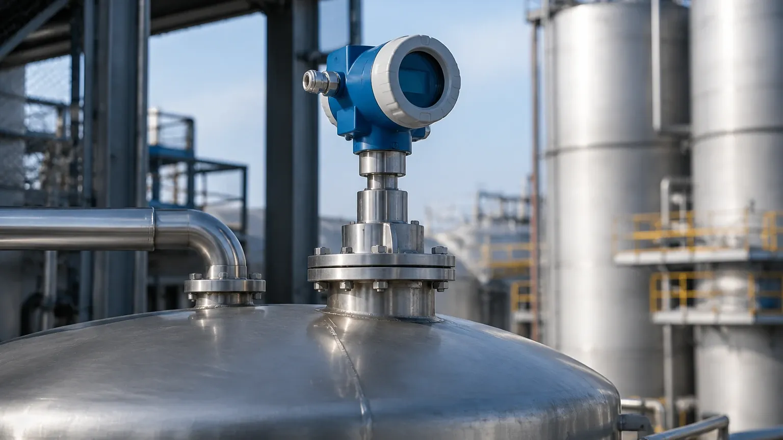
The Emerson 5301 is designed for minimal maintenance, as it has no moving parts. However, periodic verification is recommended in critical safety loops.
* Signal Quality Metrics: The transmitter provides a signal strength value. A sudden drop in signal strength often indicates probe coating or a change in the fluid's dielectric properties.
* Verification: Use the "Verification through Echo Curve" feature in the configuration software (such as Rosemount Radar Master). This allows technicians to visualize the pulse reflections and identify if the transmitter is locking onto the correct surface.
7. Buyer’s Checklist for International Procurement
When sourcing radar level transmitters for global projects, international buyers should confirm the following technical details with the manufacturer or OEM partner:
* Material Compatibility: Ensure the probe material (e.g., 316L Stainless Steel, Hastelloy, or PTFE coating) is compatible with the process chemical.
* Hazardous Area Certifications: Confirm ATEX, IECEx, or FM certifications depending on the installation region.
* Process Connection: Specify the exact flange standard (ANSI, DIN, JIS) and pressure rating.
* Probe Length: Provide the exact "L" length from the flange face to the probe tip, accounting for any dead zones at the top or bottom of the tank.
* OEM/ODM Customization: For large-scale industrial automation providers, inquire if customized housing or specialized firmware is available to integrate with proprietary control systems.
8. Frequently Asked Questions (FAQ)
Q: Can the Emerson 5301 measure solids?
A: Yes, it can measure powders and granulates using a flexible single lead probe. However, the dielectric constant of the solid must be considered, and the probe must be able to withstand the pull-down forces of the material during discharge.
Q: How does temperature affect the measurement?
A: Unlike ultrasonic sensors, radar signals are not significantly affected by changes in air temperature, pressure, or vapor composition. However, extreme temperatures can cause mechanical expansion of the probe, which the transmitter can compensate for if configured correctly.
Q: Is it possible to cut the probe in the field?
A: Yes, many probe types for the 5301 are field-cuttable. After cutting, the transmitter's configuration must be updated with the new probe length to maintain accuracy.
Conclusion
The Emerson radar level transmitter 5301 is a versatile and high-performance instrument that excels in demanding industrial environments. By guiding the radar pulse along a probe, it overcomes many of the limitations associated with non-contact measurement, such as surface turbulence and low dielectric constants. For engineers seeking to optimize their level control loops, understanding the interplay between probe selection, tank geometry, and fluid properties is the key to a successful installation. Whether for simple water storage or complex high-pressure chemical reactors, GWR technology remains a cornerstone of modern industrial level measurement.