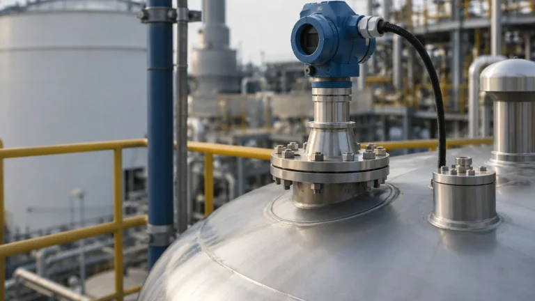
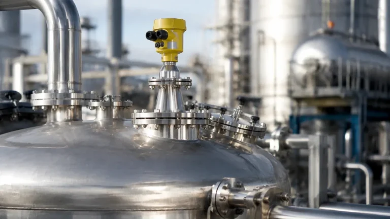
Supmea Radar Level Transmitter
Supmea Radar Level Transmitter: A Technical Engineering Guide to Non-Contact Measurement
In the landscape of industrial automation, the precision of level measurement directly impacts process efficiency, safety, and inventory management. Among the various technologies available, Radar Level Meters have emerged as the gold standard for challenging environments. Specifically, the supmea radar level transmitter represents a versatile class of instrumentation designed to handle diverse media, from corrosive chemicals to high-temperature solids.
This guide provides a comprehensive technical overview of radar level measurement principles, selection criteria for various industrial models, and the critical installation parameters required to ensure long-term reliability in B2B applications.
1. Fundamental Measurement Principles
Radar level transmitters operate on the principle of electromagnetic wave propagation. Unlike ultrasonic sensors, which rely on sound waves and are susceptible to air temperature and pressure changes, radar waves travel at the speed of light and are largely unaffected by the gas phase composition above the liquid.
1.1 Time-of-Flight (ToF) Pulse Radar
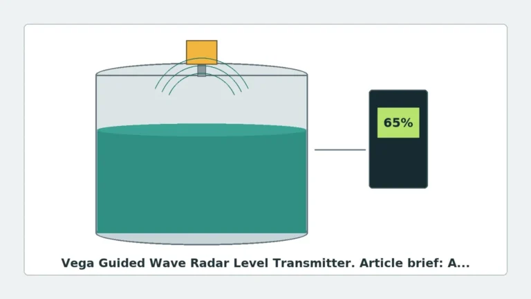
Pulse radar transmitters emit short microwave pulses toward the target material. These pulses reflect off the surface and return to the sensor's antenna. The instrument measures the time elapsed between emission and reception.
The distance ($D$) is calculated using the formula:
$$D = \frac{c \times t}{2}$$
Where:
* c is the speed of light (approx. 300,000 km/s).
* t is the measured transit time.
1.2 Frequency Modulated Continuous Wave (FMCW)
Modern high-precision transmitters, such as the 80GHz variants, often utilize FMCW technology. Instead of discrete pulses, the transmitter emits a continuous signal with a constantly changing frequency. The difference in frequency between the emitted and received signal is proportional to the distance. FMCW offers superior signal-to-noise ratios, allowing for more accurate measurements in narrow tanks or through heavy dust.
2. Technical Comparison: 26GHz vs. 80GHz Technology
When selecting a supmea radar level transmitter, the operating frequency is the most critical technical specification. It dictates the beam angle, sensitivity, and the ability to penetrate obstacles.
| Feature | 26GHz Radar (K-Band) | 80GHz Radar (W-Band) |
| :— | :— | :— |
| Beam Angle | Typically 8° to 12° | Narrow 3° to 6° |
| Accuracy | ±3mm to ±5mm | ±1mm to ±2mm |
| Max Range | Up to 30m – 70m | Up to 120m |
| Nozzle Size | Requires larger nozzles (DN80+) | Works with small nozzles (DN25+) |
| Obstacle Handling | Moderate; requires careful placement | Excellent; avoids internal structures |
| Dust/Steam | Good penetration | Superior signal processing |
Why Frequency Matters
The beam angle is inversely proportional to the frequency and the antenna diameter. A narrower beam (80GHz) ensures that the energy is concentrated on the product surface rather than reflecting off tank walls, ladders, or agitators. This makes the 80GHz supmea radar level transmitter the preferred choice for complex vessel geometries.
3. The Role of the Dielectric Constant ($ε_r$)
The reliability of any radar measurement depends on the dielectric constant of the medium. The dielectric constant ($ε_r$) measures the ability of a material to reflect electromagnetic energy.
* High $ε_r$ (>10): Materials like water, acids, and bases provide strong reflections and are easy to measure.
* Low $ε_r$ (1.4 to 4): Materials like hydrocarbons, oils, and certain plastic pellets reflect very little energy.
For low-dielectric materials, engineers must select transmitters with high sensitivity or consider Guided Wave Radar (GWR) if the process allows contact. However, modern high-frequency non-contact radar can often overcome low $ε_r$ challenges through advanced signal processing and larger antenna gains.
4. Selection Criteria for Industrial Applications
Choosing the correct model requires an analysis of the physical and chemical environment of the tank. Use the following table as a preliminary selection guide for industrial radar units.
| Application Environment | Recommended Transmitter Type | Key Feature |
| :— | :— | :— |
| Standard Water/Wastewater | 26GHz Pulse Radar | Cost-effective, reliable |
| Corrosive Chemical Tanks | PTFE-coated Horn/Flange | Chemical resistance |
| Cement/Grain Silos | 80GHz FMCW (Lens Antenna) | Dust penetration, narrow beam |
| High-Pressure Vessels | Sealed Flange / 26GHz | Pressure ratings up to 40 Bar |
| Sanitary (Food/Pharma) | 80GHz with Flush Diaphragm | No dead zones, easy cleaning |
5. Installation Best Practices
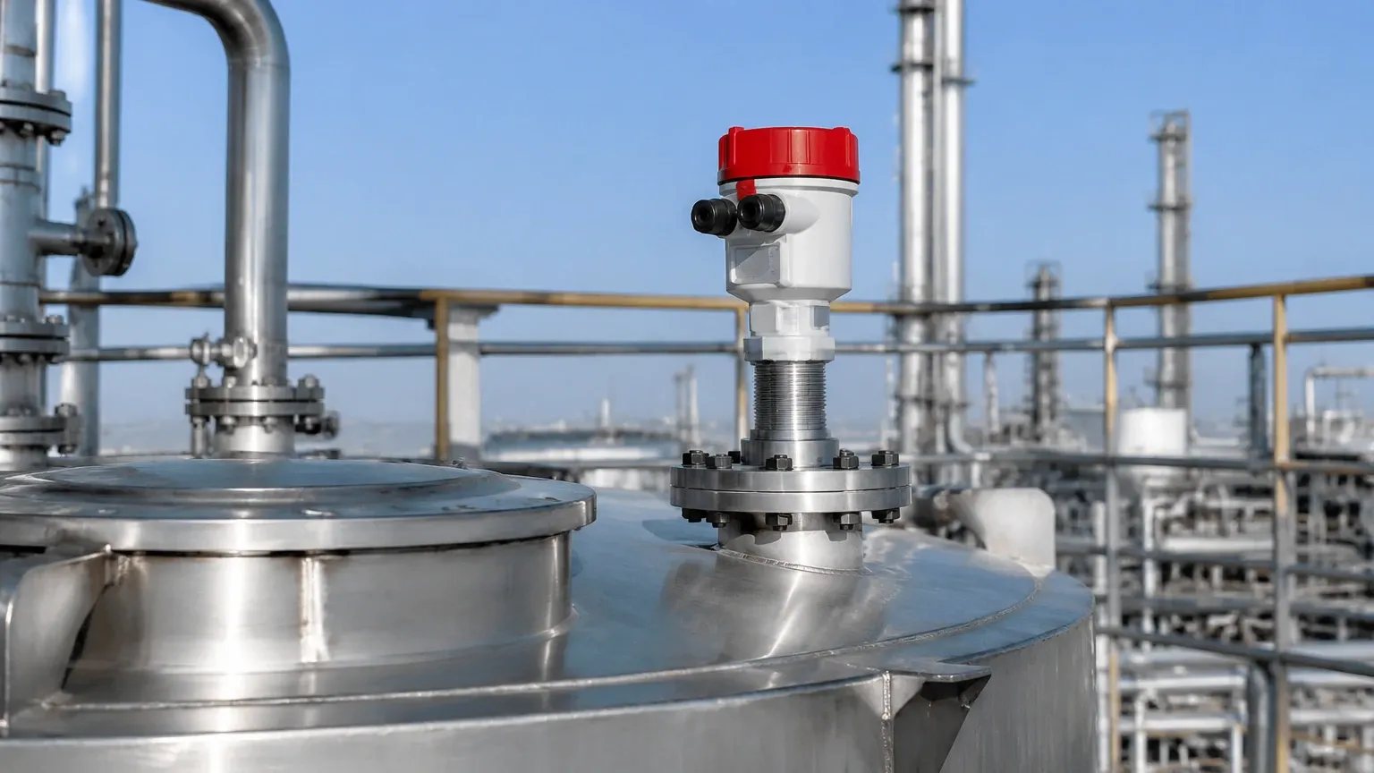
Even the most advanced supmea radar level transmitter will fail if installed incorrectly. Engineers must adhere to the following geometric constraints:
5.1 Nozzle Height and Diameter
The antenna should ideally extend beyond the bottom of the mounting nozzle to prevent internal reflections. If the nozzle is long and narrow, the radar signal may experience "ringing," creating a false high-level reading.
5.2 Distance from Tank Wall
Radar sensors should not be mounted in the center of a tank (to avoid multiple reflections) nor too close to the wall. A general rule is to maintain a distance of at least 200mm from the vessel wall or 1/6th of the tank diameter.
5.3 Avoiding Obstructions
The "signal beam" is a cone. Anything within this cone—such as heating coils, ladders, or inflow streams—will cause interference. If obstructions are unavoidable, most modern transmitters offer a "False Echo Suppression" or "Background Learning" function to map out and ignore these static reflections.
5.4 The Blind Zone (Dead Band)
Every radar sensor has a minimum measurable distance near the antenna, typically ranging from 50mm to 300mm. If the liquid level enters this zone, the measurement becomes unreliable. Ensure the transmitter is mounted high enough to accommodate the maximum expected fill level.
6. Application Risks and Limitations
While radar is highly versatile, it is not a universal solution. Engineers should be aware of the following risks:
1. Heavy Foam: Dense, thick foam (like that in a protein skimmer or certain fermentation processes) can absorb the radar signal entirely, leading to a "Loss of Echo" (LOE) error.
2. Turbulent Surfaces: Rapidly boiling liquids or high-speed agitators can scatter the signal. This can often be mitigated by increasing the damping (integration time) in the transmitter settings.
3. Condensation and Buildup: While 80GHz lens antennas are designed to shed droplets, heavy crystalline buildup on the antenna face will eventually attenuate the signal. In these cases, a transmitter with a purging (air cleaning) port is recommended.
7. Configuration and Commissioning
Modern Radar Level Meters are typically configured via HART protocol, Bluetooth, or a local display interface. Key parameters to set during commissioning include:
* Tank Height (Full Scale): The distance from the sensor face to the 0% (bottom) point.
* Measuring Range: The 100% (full) point.
* Damping Time: Usually set between 1 to 10 seconds to smooth out surface fluctuations.
* Application Type: Selecting "Liquid" or "Solid" changes the internal signal processing algorithms to better suit the reflection characteristics of the medium.
8. Frequently Asked Questions (FAQ)
Q: Can a radar level transmitter measure through a plastic tank roof?
A: Yes. If the tank is made of a non-conductive material like PE, PP, or PVC and has no metal reinforcement, the radar signal can penetrate the roof. This allows for "non-invasive" measurement, though some signal strength is lost (typically 10-20%).
Q: Does vacuum affect radar measurement?
A: No. Unlike ultrasonic sensors which require a medium (air) to transmit sound, radar waves are electromagnetic and travel perfectly through a vacuum. This makes them ideal for vacuum distillation columns.
Q: How often does a supmea radar level transmitter require calibration?
A: Because there are no moving parts and the technology is based on the constant speed of light, radar transmitters do not "drift" in the traditional sense. Most industrial users perform a verification check once a year, but full recalibration is rarely necessary unless the process conditions change significantly.
Q: What is the difference between 2-wire and 4-wire transmitters?
A: 2-wire (Loop-powered) units use the same pair of wires for power and the 4-20mA signal, simplifying wiring. 4-wire units have separate power and signal lines, which is often necessary for high-power 80GHz units or when integrated heaters/backlit displays are required.
Conclusion
The integration of a supmea radar level transmitter into an industrial process provides a leap in data reliability compared to traditional mechanical or ultrasonic methods. By understanding the nuances of frequency selection, dielectric properties, and installation geometry, plant engineers can specify a solution that minimizes maintenance and maximizes uptime. Whether dealing with the extreme dust of a clinker silo or the precise requirements of a chemical reactor, modern radar technology offers the robustness required for today's automated industrial environments.