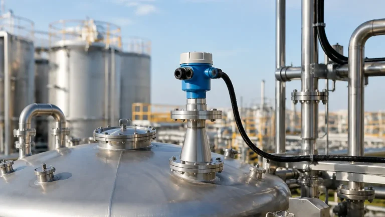
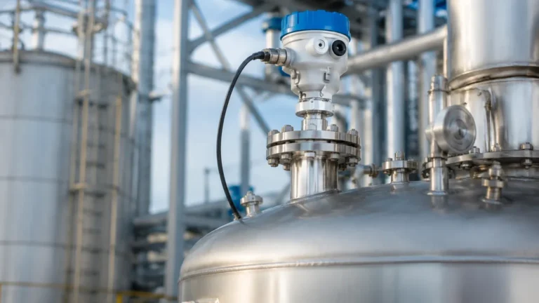
Yokogawa Guided Wave Radar Level Transmitter
Yokogawa Guided Wave Radar Level Transmitter: Engineering Principles and Selection Guide
In the landscape of industrial process control, accurate level measurement is fundamental to safety, efficiency, and inventory management. Among the various technologies available, the guided wave radar (GWR) transmitter stands out for its reliability in challenging environments. This guide examines the engineering principles, selection criteria, and installation requirements for high-performance instrumentation, with a specific focus on the capabilities associated with the yokogawa guided wave radar level transmitter and broader Radar Level Meters technology.
1. Understanding the Measurement Principle
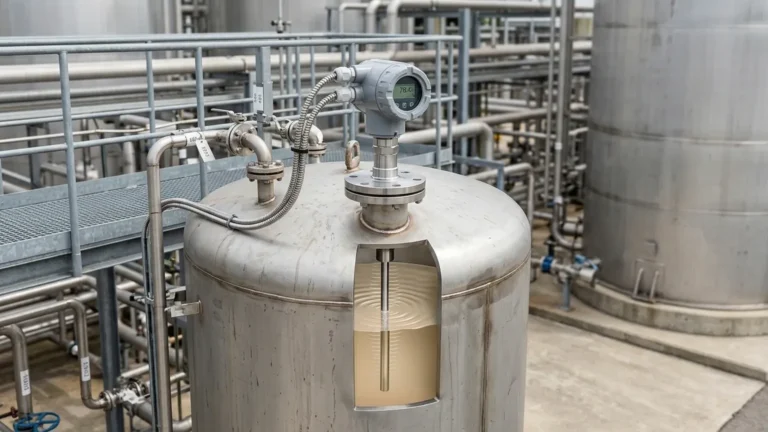
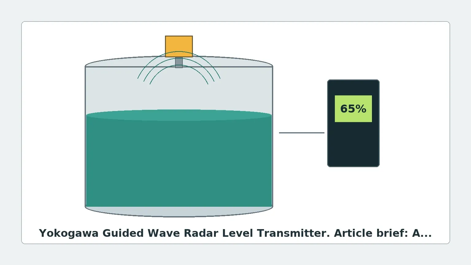
Guided Wave Radar technology is based on the principle of Time Domain Reflectometry (TDR). Unlike non-contact radar, which emits electromagnetic waves through the air, GWR utilizes a physical probe (a waveguide) to direct the signal from the transmitter head to the process medium.
The TDR Process
1. Pulse Emission: The transmitter electronics generate low-power microwave pulses.
2. Propagation: These pulses travel down the probe at the speed of light.
3. Reflection: When the pulse reaches the surface of the medium (liquid or solid), a change in the dielectric constant ($ε_r$) causes a change in impedance. This triggers a reflection of the pulse back up the probe.
4. Time-of-Flight Calculation: The transmitter measures the time interval between the emission of the pulse and the reception of the return signal. Since the speed of light is constant, the distance is calculated as:
*Distance = (Speed of Light × Time of Flight) / 2*
5. Level Conversion: The device subtracts the measured distance from the total tank height (reference point) to determine the actual level of the medium.
Because the pulse is contained and guided by the probe, the signal is less susceptible to attenuation caused by foam, dust, or turbulent surfaces compared to non-contact radar systems.
2. Technical Features of the Yokogawa Guided Wave Radar Level Transmitter
The yokogawa guided wave radar level transmitter is engineered for high-demand industrial applications. These devices are typically characterized by their robust signal processing and diagnostic capabilities. Key technical features often include:
* Dynamic Signal Tracking: Advanced algorithms that can distinguish between the actual level reflection and "noise" generated by internal tank obstructions or probe coating.
* Multi-Variable Output: Many models can simultaneously measure the total level and the interface level (e.g., the boundary between oil and water).
* Digital Communication: Support for industry-standard protocols such as HART, FOUNDATION Fieldbus, and PROFIBUS PA, allowing for seamless integration into Distributed Control Systems (DCS).
* High Pressure and Temperature Ratings: Designed to operate in conditions exceeding 400°C (752°F) and pressures up to 400 bar (5800 psi), depending on the specific probe and seal configuration.
3. Probe Selection and Application Table
Selecting the correct probe is critical for the performance of a GWR system. The choice depends on the dielectric constant of the medium, the presence of obstacles, and the physical properties of the liquid or solid.
| Probe Type | Best Use Case | Dielectric Constant (ε_r) | Advantages | Limitations |
| :— | :— | :— | :— | :— |
| Single Rod / Cable | Liquids with high ε_r, viscous fluids | > 10 (Direct), > 1.4 (with TBF) | Easy to clean, resistant to coating | Weakest signal; sensitive to tank walls |
| Twin Rod / Cable | Low ε_r liquids, long ranges | > 1.9 | Stronger signal than single rod | Prone to bridging/clogging between rods |
| Coaxial | Low ε_r liquids, turbulent surfaces | > 1.4 | Highest signal-to-noise ratio; immune to tank internals | Only for clean, low-viscosity liquids |
*Note: TBF (Tank Bottom Following) is a software feature used when the signal from the surface is too weak to detect directly due to very low dielectric constants.*
4. Installation Considerations and Constraints
To ensure the accuracy of Radar Level Meters, engineers must adhere to specific installation guidelines. Even the most advanced yokogawa guided wave radar level transmitter can provide erroneous readings if improperly mounted.
Nozzle Geometry
The nozzle diameter and height play a significant role. For coaxial probes, nozzle dimensions are less critical. However, for single and twin probes, the nozzle should be as short and wide as possible to minimize "ringing" or parasitic reflections near the top of the probe. A typical rule of thumb is that the nozzle height should not exceed its diameter.
Clearance from Tank Walls and Obstructions
* Single Probes: Must be kept at a minimum distance from the tank wall (typically 100 mm to 300 mm or 4 to 12 inches) to prevent signal interference.
* Internal Obstacles: Probes should be installed away from agitators, heating coils, and ladders. If an obstruction is within the "signal cone" of the probe, it may cause a false high-level reading.
* Inlet Flow: Never install the probe directly under a fill stream. The force of the incoming liquid can damage the probe or create excessive turbulence that disrupts the signal.
Grounding and Stability
The transmitter must be properly grounded to the tank (if metal) to ensure a consistent reference for the electromagnetic pulse. For non-metallic tanks, a bypass pipe or a special grounding plate may be required.
5. Industrial Applications
Oil and Gas: Interface Measurement
One of the primary uses of the yokogawa guided wave radar level transmitter is in separators. Because the microwave pulse can partially pass through a low-dielectric upper layer (like oil) and reflect off a high-dielectric lower layer (like water), GWR is the gold standard for measuring interface levels in real-time.
Chemical Processing: Corrosive Environments
In tanks containing acids or bases, probes are often coated with PFA or PTFE. This protection ensures longevity while maintaining the conductive properties required for the TDR pulse to propagate effectively.
Power Generation: Steam Drums
High-pressure steam drums require precise level control to prevent boiler damage. GWR transmitters with specialized high-temperature ceramic seals and steam compensation features are used to provide accurate readings despite the changing density of steam at high pressures.
6. Limitations and Risks
While highly versatile, GWR technology is not a universal solution. Engineers should be aware of the following limitations:
1. Dielectric Constant (ε_r) Requirements: If the medium has a dielectric constant below 1.4, the reflection may be too weak for standard detection. In these cases, a coaxial probe or TBF software is mandatory.
2. Probe Coating and Bridging: In extremely viscous or "sticky" applications, material can build up between twin rods or inside a coaxial probe. This "bridging" creates a false level signal at the point of the buildup.
3. Mechanical Stress: In tall silos or high-flow tanks, horizontal forces can bend or break rigid rod probes. Flexible cable probes with end-weights are preferred for heights exceeding 6 meters (approx. 20 ft).
7. Frequently Asked Questions (FAQs)
Q: Can a guided wave radar measure solids like powders or grains?
A: Yes, GWR is effective for solids, but cable probes are typically used to withstand the pull-down forces of the material. The dielectric constant of the solid must also be considered, as many dry powders have very low ε_r values.
Q: How does foam affect the measurement?
A: Generally, GWR is superior to non-contact radar in foamy conditions. While dense, thick foam may cause a slight signal delay or a false reflection, most process foam is transparent to the microwave pulse, allowing the device to see through to the true liquid level.
Q: Is calibration required on-site?
A: Most modern transmitters are pre-calibrated from the factory based on the probe length provided. However, a "zero-point" check and a span verification are recommended during commissioning to account for specific tank geometry.
Q: Can the probe be shortened in the field?
A: Many cable and rod probes are designed to be field-cut. However, the transmitter electronics must be updated with the new probe length to maintain accuracy. Coaxial probes are generally more difficult to modify in the field.
8. Conclusion for International Buyers
When specifying a yokogawa guided wave radar level transmitter or any high-end Radar Level Meters, international buyers should confirm the following data points with their supplier:
* Process Medium Properties: Specifically the minimum dielectric constant and viscosity.
* Operating Envelope: Maximum and minimum temperature and pressure.
* Tank Drawing: To identify potential obstructions and determine the optimal probe length and mounting position.
* Certification Requirements: Ensure the device meets local explosion-proof (ATEX, IECEx, FM) and functional safety (SIL) standards.
By understanding the underlying TDR physics and carefully matching the probe geometry to the application, engineers can implement a level measurement solution that provides years of maintenance-free operation in even the most rigorous industrial environments.
Download Yokogawa Guided Wave Radar Level Transmitter as a PDF