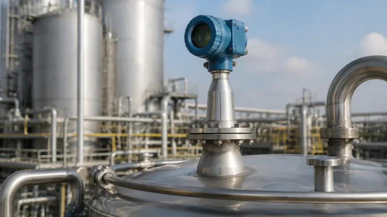
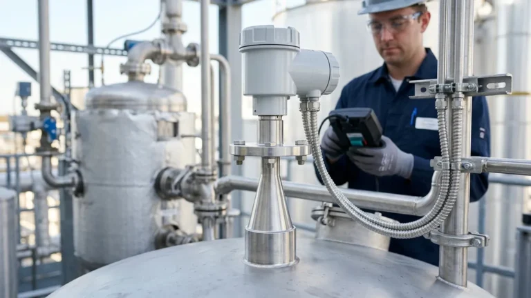
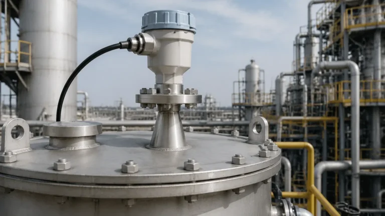
Yokogawa Radar Level Transmitter
Yokogawa Radar Level Transmitter: A Practical Engineering Guide to Selection and Application
In the landscape of industrial process automation, non-contact level measurement has become the preferred standard for challenging environments. Among the most reliable instruments in this category is the yokogawa radar level transmitter, a device engineered to provide high-precision measurements in liquid and solid applications. Whether dealing with corrosive chemicals, high-temperature hydrocarbons, or simple water treatment tanks, understanding the engineering nuances of radar technology is essential for ensuring long-term operational stability.
This guide explores the measurement principles, selection criteria, and installation requirements for Radar Level Meters, providing international buyers and engineers with the technical foundation needed to specify the correct equipment for their specific process conditions.
1. Measurement Principles: FMCW vs. Pulse Radar
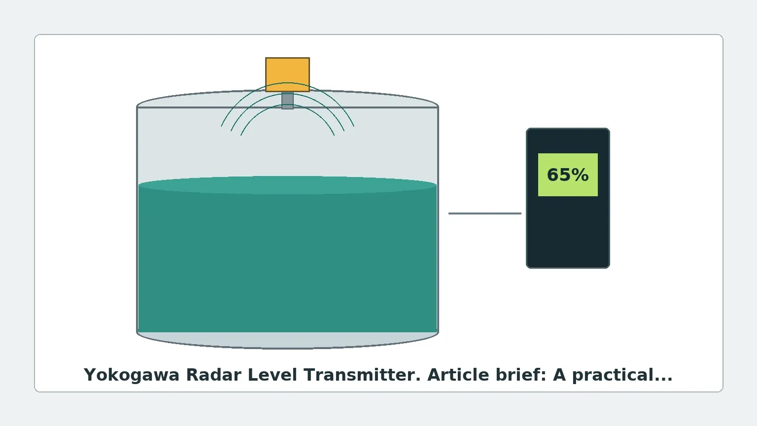
Before selecting a yokogawa radar level transmitter, it is vital to distinguish between the two primary methods of radar measurement: Pulse Radar and Frequency Modulated Continuous Wave (FMCW).
Pulse Radar (Time of Flight)
Pulse radar transmitters emit a short microwave signal and measure the time it takes for the pulse to travel to the product surface and return to the sensor. The distance is calculated using the constant speed of light. While effective for simple applications, pulse radar often has a lower signal-to-noise ratio compared to modern FMCW systems.
FMCW Radar (Frequency Modulation)
Most high-performance radar transmitters, including several models in the Yokogawa lineup, utilize FMCW technology. Instead of a single pulse, the transmitter emits a continuous signal with a constantly changing frequency. The difference in frequency between the transmitted signal and the reflected signal is proportional to the distance. FMCW offers several engineering advantages:
* Higher Accuracy: Better resolution in measuring small changes in level.
* Signal Processing: Superior ability to filter out "false echoes" caused by tank internals like agitators or ladders.
* Low Dielectric Performance: Enhanced capability to detect surfaces with low reflectivity (low dielectric constants).
2. Frequency Selection: 6GHz, 26GHz, and 80GHz
The frequency of the microwave signal determines the beam angle and the instrument's ability to penetrate vapor or dust. When evaluating Radar Level Meters, frequency is perhaps the most critical technical specification.
* 6 GHz (C-Band): These transmitters have a wider beam and are less affected by foam or heavy turbulence. They are often used in large tanks where the wide beam won't hit the walls.
* 26 GHz (K-Band): A versatile middle ground used for most standard liquid applications. It offers a narrower beam than C-band, allowing for installation in smaller nozzles.
* 80 GHz (W-Band): The current state-of-the-art for precision. The 80 GHz frequency allows for an extremely narrow beam angle (often as low as 3 degrees). This makes it ideal for tall, narrow silos or tanks with complex internal structures, as the beam can easily bypass obstructions.
3. Engineering Selection Criteria
Selecting a yokogawa radar level transmitter requires a detailed analysis of the process environment. Engineers should use the following parameters to narrow down their choices:
Dielectric Constant ($ε_r$)
The dielectric constant of the medium determines how much of the radar signal is reflected. Water has a high dielectric constant (~80) and is easy to measure. Hydrocarbons like oil or solvents often have low dielectric constants (<2.0), which absorb more of the signal. For low $ε_r$ media, high-sensitivity FMCW transmitters or Guided Wave Radar (GWR) may be required.
Process Temperature and Pressure
Standard radar antennas are often rated for temperatures up to 150°C (302°F) and pressures up to 40 bar (580 psi). However, specialized high-temperature versions can handle up to 450°C (842°F). It is critical to confirm that the flange and sealing materials (such as Kalrez or Viton) are compatible with the process chemistry at these extremes.
Measuring Range
While some radar meters can measure up to 120 meters (393 ft), accuracy often degrades at the very top and bottom of the range. Engineers must account for the "Dead Zone" or "Blocking Distance" near the antenna where measurement is not possible.
4. Installation Constraints and Best Practices
Even the most advanced yokogawa radar level transmitter will fail to perform if installed incorrectly. Follow these engineering guidelines to ensure signal integrity:
| Consideration | Requirement | Engineering Logic |
| :— | :— | :— |
| Nozzle Height | Minimum 50mm – 200mm | Prevents the antenna from being recessed too far, which causes "ringing" or signal interference. |
| Wall Distance | >200mm (8 in) | Prevents the beam from reflecting off the tank wall rather than the liquid surface. |
| Obstructions | Clear path required | Avoid placing the transmitter directly above heating coils, ladders, or agitator blades. |
| Inlet Flow | Avoid turbulence | Do not install the meter directly above the product inlet pipe to avoid surface fluctuations. |
| Orientation | Perpendicular to surface | The antenna must be level to ensure the signal reflects directly back to the receiver. |
Nozzle and Beam Angle
When using a 26GHz transmitter, a 3-inch nozzle is typically required to accommodate the beam angle. With an 80GHz transmitter, a 1-inch or 1.5-inch nozzle is often sufficient because the beam is much more concentrated. This can significantly reduce installation costs in new vessel designs.
5. Application Risks and Limitations
While radar is highly versatile, it is not a universal solution. Engineers should be aware of the following risks:
1. Heavy Foam: Dense, thick foam (like shaving cream) can absorb the radar signal entirely, leading to a "Loss of Echo" (LOE) error. In these cases, a mechanical level gauge or a low-frequency radar may be more appropriate.
2. Condensation and Buildup: While many Yokogawa antennas feature a PTFE drop-off design to shed moisture, extreme condensation or sticky buildup can attenuate the signal. Air purging systems are often recommended for these environments.
3. Multiple Interfaces: Non-contact radar measures the top surface. If you need to measure the interface between oil and water, Guided Wave Radar (GWR) is the correct choice, as it can penetrate the upper layer.
4. Vacuum Conditions: While radar works in a vacuum (unlike ultrasonic sensors), the mechanical seals of the transmitter must be rated for vacuum service to prevent air ingress or sensor damage.
6. Practical Selection Table for Radar Technologies
| Feature | 6 GHz Radar | 26 GHz Radar | 80 GHz Radar | Guided Wave Radar |
| :— | :— | :— | :— | :— |
| Primary Use | Large tanks, foam | Standard liquids | Narrow silos, solids | Interface, low $ε_r$ |
| Beam Angle | Wide (20°+) | Medium (8-10°) | Narrow (3-4°) | N/A (Contact) |
| Accuracy | ±5mm to ±10mm | ±2mm to ±5mm | ±1mm | ±2mm |
| Dust Resistance | Excellent | Good | Fair (requires purge) | Excellent |
| Installation | Large nozzles | Standard nozzles | Small nozzles | Requires probe |
7. Frequently Asked Questions (FAQ)
Q: Can a yokogawa radar level transmitter be used in plastic tanks?
A: Yes. Radar signals can pass through plastic (non-conductive) materials. In some cases, the transmitter can be mounted outside the tank, looking through a plastic window or the tank roof, though signal attenuation must be calculated.
Q: How does the dielectric constant affect the accuracy?
A: The dielectric constant doesn't necessarily change the accuracy, but it changes the signal strength. If the $ε_r$ is too low, the signal may be too weak to distinguish from background noise, leading to intermittent readings.
Q: Is calibration required on-site?
A: Most modern radar transmitters are pre-calibrated at the factory. However, "mapping" the tank is usually required during commissioning. This process tells the transmitter to ignore fixed reflections from internal tank structures.
Q: What is the difference between 2-wire and 4-wire transmitters?
A: 2-wire transmitters are powered by the 4-20mA loop, simplifying wiring. 4-wire transmitters have a separate power supply and are typically used when high-power signal processing or heated displays are required.
8. Conclusion for International Procurement
When specifying a yokogawa radar level transmitter, the success of the installation depends on a complete data sheet. International buyers should ensure they provide the manufacturer with the tank height, nozzle dimensions, chemical composition, minimum/maximum temperature, and the presence of any internal obstructions.
By selecting the appropriate frequency and antenna type, and adhering to strict installation geometries, radar level measurement provides a maintenance-free solution that enhances both safety and process efficiency. For those looking to compare specific models or explore customized OEM options for various industrial sectors, it is advisable to Review product options and application support to ensure the selected hardware aligns with the specific dielectric and atmospheric challenges of the site.