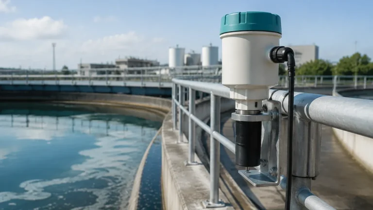
An Ultrasonic Meter Operates on What Principle
An Ultrasonic Meter Operates on What Principle: A Comprehensive Engineering Guide
In the realm of industrial automation and process control, selecting the right level measurement technology is critical for operational efficiency and safety. Among the various technologies available, ultrasonic sensors have become a staple due to their non-contact nature and versatility. However, for engineers and procurement specialists, understanding the underlying physics is essential for proper application. This guide explores the fundamental question: an ultrasonic meter operates on what principle, and how does this translate to real-world industrial performance?
The Core Principle: Time-of-Flight (ToF)
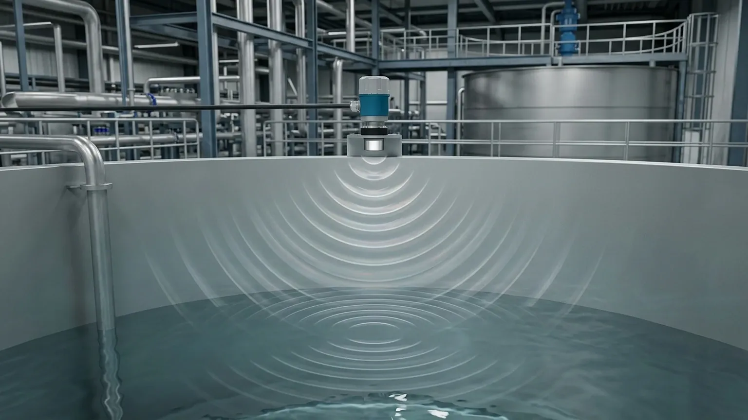
At its most fundamental level, an ultrasonic meter operates on the Time-of-Flight (ToF) principle, also frequently referred to as the echo-ranging principle. This method relies on the transmission and reception of high-frequency sound waves—typically above the range of human hearing (20 kHz to 200 kHz)—to determine the distance between the sensor and the surface of a material.
The Measurement Cycle
1. Emission: The sensor’s transducer contains piezoelectric crystals. When an electrical pulse is applied, these crystals vibrate, generating a burst of ultrasonic sound waves. These waves travel through the air (or other gas) toward the target material.
2. Reflection: Once the sound waves hit the surface of the liquid or solid, they are reflected back toward the sensor. This reflected signal is known as the "echo."
3. Detection: The transducer, now acting as a receiver, detects the returning echo. The piezoelectric crystal converts the mechanical energy of the sound wave back into an electrical signal.
4. Calculation: The internal electronics of the Ultrasonic Level Meters measure the exact time interval between the emission of the pulse and the reception of the echo.
The Mathematical Formula
The distance ($D$) from the sensor to the material surface is calculated using the following formula:
$$D = \frac{c \times t}{2}$$
Where:
* $c$: The speed of sound in the medium (approximately 343 m/s in air at 20°C).
* $t$: The total transit time (the time taken for the pulse to travel to the surface and back).
The distance is divided by two because the time measured represents the round trip of the sound wave. To determine the actual level ($L$) of the material in a tank, the device subtracts the measured distance ($D$) from the total height of the tank or the sensor's mounting position ($E$):
$$L = E – D$$
Factors Affecting the Speed of Sound
Because the measurement is entirely dependent on the speed of sound, any factor that changes that speed will affect the accuracy of the meter. The most significant factor is temperature. As temperature increases, the speed of sound increases. Most professional-grade instruments, such as those manufactured by Welk, include integrated temperature sensors to provide automatic compensation, ensuring accuracy remains within ±0.25% to ±0.5% of the measured range.
Other factors include:
* Gas Composition: Sound travels at different speeds through different gases (e.g., Carbon Dioxide vs. Nitrogen). If the vapor space in a tank is not air, the meter must be calibrated for that specific gas.
* Humidity: While humidity has a minor effect compared to temperature, extreme changes in moisture content can influence sound velocity.
Practical Selection Criteria for Industrial Applications
When selecting an ultrasonic meter, engineers must match the sensor specifications to the specific requirements of the process. The following table provides a guideline for typical selection criteria.
Selection Table: Ultrasonic Level Meter Specifications
| Feature | Requirement / Specification | Application Context |
| :— | :— | :— |
| Measurement Range | 0.3m to 30m (standard) | Short-range for small tanks; long-range for silos. |
| Beam Angle | 5° to 12° | Narrower beams are better for avoiding internal tank obstructions. |
| Operating Temperature | -40°C to +80°C | Standard range for most outdoor and indoor industrial tanks. |
| Output Signal | 4-20mA, RS485 (Modbus), HART | Integration with PLC/SCADA systems. |
| Housing Material | ABS, PVDF, or Stainless Steel | PVDF is preferred for corrosive chemical storage. |
| Accuracy | ±0.25% to ±0.5% of span | Critical for inventory management and billing. |
Installation Considerations and Best Practices
Understanding the principle of operation also highlights why certain installation practices are mandatory. Since the meter relies on a clear path for sound waves, the following guidelines are essential:
1. The "Dead Band" (Blocking Distance)
Every ultrasonic sensor has a "dead band" or blocking distance immediately below the transducer face (typically 0.2m to 0.6m depending on the frequency). In this zone, the transducer cannot switch from "transmit" to "receive" mode fast enough to capture the echo. The maximum liquid level must never enter this dead band, or the meter will provide erratic readings.
2. Mounting Position
* Avoid the Center: In cylindrical tanks with domed tops, mounting the sensor in the exact center can create a "parabolic" effect, where reflected echoes are amplified and cause false readings.
* Perpendicularity: The transducer face must be perfectly parallel to the liquid surface. A tilt of even a few degrees can cause the echo to bounce away from the sensor rather than back to it.
* Avoid the Wall: Do not mount the sensor too close to the tank wall, as the beam spreads out (the beam angle). If the beam hits the wall, it creates "ghost echoes."
3. Obstruction Management
Internal structures like ladders, heating coils, or agitators can interfere with the sound path. If obstructions cannot be avoided, many modern transmitters offer "False Echo Suppression" software, allowing the user to map out and ignore static reflections.
Limitations and Prohibitions
While ultrasonic technology is robust, it is not a universal solution. Its reliance on sound waves through a gaseous medium leads to specific limitations:
* Vacuum Applications: Sound cannot travel through a vacuum. For vacuum tanks, radar or hydrostatic transmitters must be used.
* Heavy Foam: Dense foam on the surface of a liquid acts as an acoustic absorber. It soaks up the sound energy rather than reflecting it, leading to a "Loss of Echo" (LOE) error.
* High Pressure/High Temperature: At very high pressures, the density of the gas changes significantly, and at very high temperatures (above 100°C), the transducer materials may degrade. In these cases, guided wave radar is often a better choice.
* Heavy Dust: In solid level measurement (e.g., flour or cement silos), heavy dust can attenuate the signal. High-power, low-frequency ultrasonic sensors are required for these environments.
Comparison: Ultrasonic vs. Other Technologies
| Technology | Principle | Best For | Main Limitation |
| :— | :— | :— | :— |
| Ultrasonic | Sound Echo (ToF) | Water, Wastewater, Chemicals | Foam, Vacuum, High Temp |
| Radar (Non-contact) | Electromagnetic Waves | High Temp, High Pressure | Cost, Dielectric Constant |
| Hydrostatic | Pressure at Bottom | Vented Tanks, Constant Density | Moving Parts (if submersible) |
| Magnetic Gauge | Buoyancy/Magnetism | Visual Indication, High Pressure | Liquid only, Mechanical wear |
Frequently Asked Questions (FAQ)
Q: Can ultrasonic meters measure the level of solids?
A: Yes, but with caveats. Solids like grain, sand, or plastic pellets do not reflect sound as uniformly as liquids. They often have an "angle of repose," which can deflect the echo. For solids, sensors with higher power and narrower beam angles are typically required.
Q: How does wind or air turbulence affect the measurement?
A: Strong air currents can "blow" the sound wave away or cause fluctuations in the air density. In outdoor tanks or highly turbulent environments, a stilling well (a pipe that shields the measurement area) is often recommended to stabilize the signal.
Q: What is the difference between an ultrasonic transmitter and an ultrasonic switch?
A: An ultrasonic transmitter (or meter) provides continuous measurement (e.g., 4-20mA signal representing 0-100% level). An ultrasonic switch is a point-level device that only triggers an alert when the material reaches a specific height.
Q: Does the color or transparency of the liquid matter?
A: No. Unlike optical or laser sensors, ultrasonic meters are unaffected by the color, transparency, or opacity of the liquid. They only care about the physical surface that reflects the sound wave.
Conclusion
An ultrasonic meter operates on the principle of Time-of-Flight, using the speed of sound to calculate distance. This makes it an exceptionally reliable tool for a wide range of B2B applications, particularly in water treatment, chemical processing, and industrial automation. By understanding the physics of sound propagation and respecting the environmental limitations of the technology, engineers can implement level measurement solutions that are both accurate and low-maintenance. For those requiring precise, non-contact instrumentation, Ultrasonic Level Meters remain one of the most cost-effective and proven technologies in the modern industrial landscape.
Download An Ultrasonic Meter Operates on What Principle as a PDF