Ge Ultrasonic Gas Flow Meter
GE Ultrasonic Gas Flow Meter and Ultrasonic Level Meters: A Comprehensive Engineering Guide
In the landscape of industrial process control, ultrasonic technology has emerged as a cornerstone for non-invasive, reliable measurement. Whether managing the flow of natural gas in a pipeline or monitoring the inventory of a chemical storage tank, ultrasonic instruments offer distinct advantages over mechanical alternatives. This guide explores the technical foundations, application specificities, and selection criteria for two critical categories: the GE ultrasonic gas flow meter and industrial Ultrasonic Level Meters.
Understanding the Principles of Ultrasonic Measurement
Ultrasonic measurement relies on the propagation of high-frequency sound waves (typically above 20 kHz) through a medium. However, the application of these waves differs significantly between flow measurement and level measurement.
Transit-Time Principle (Flow Measurement)
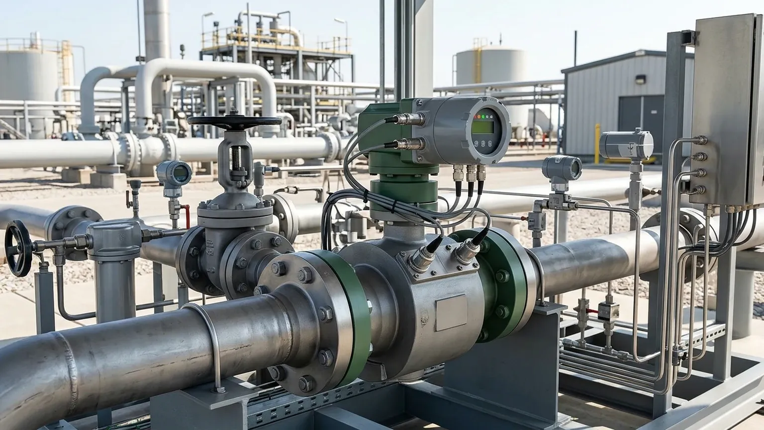
Most gas flow meters, such as the GE ultrasonic gas flow meter series, utilize the transit-time principle. This method employs pairs of transducers, each acting as both a transmitter and a receiver. One transducer sends a signal upstream while the other sends one downstream. Because the moving gas carries the sound waves, the pulse traveling downstream reaches the opposite transducer faster than the pulse traveling upstream. The difference in these transit times is directly proportional to the flow velocity of the gas. Advanced digital signal processing then calculates the volumetric flow rate based on the pipe geometry.
Pulse-Echo Principle (Level Measurement)
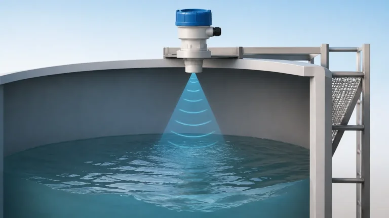
In contrast, ultrasonic level meters operate on the pulse-echo or "Time-of-Flight" (ToF) principle. A transducer mounted at the top of a vessel emits a series of ultrasonic pulses toward the material surface. These pulses reflect off the surface and return to the transducer. By measuring the time interval between transmission and reception, and knowing the speed of sound in the air or gas space above the material, the device calculates the distance to the surface. This distance is then subtracted from the total tank height to determine the level.
The Role of GE Ultrasonic Gas Flow Meters in Industry
GE (now under the Baker Hughes Panametrics brand) has long been a leader in ultrasonic gas flow measurement. These instruments are engineered for high-performance environments where accuracy and low maintenance are paramount.
Key Applications
1. Flare Gas Measurement: One of the most challenging applications in oil and gas. The GE ultrasonic gas flow meter is designed to handle high-velocity flows, varying gas compositions, and low pressures typical of flare headers.
2. Custody Transfer: High-accuracy multi-path meters are used for the fiscal measurement of natural gas, where even a 0.5% error can result in significant financial discrepancies.
3. Process Gas Monitoring: Used in chemical plants to monitor the flow of nitrogen, oxygen, or hydrogen without causing pressure drops.
Technical Advantages
* No Moving Parts: Unlike turbine or PD meters, there is no mechanical wear, reducing long-term maintenance costs.
* Wide Turndown Ratio: They can measure extremely low and extremely high velocities accurately within the same pipe.
* Bi-directional Flow: The transit-time method naturally supports measuring flow in both directions.
Engineering Guide to Ultrasonic Level Meters
While GE specializes in flow, manufacturers like Welk focus on the precision of level measurement. Ultrasonic Level Meters are the preferred choice for non-contact liquid and solid level detection in water treatment, chemical processing, and industrial automation.
Why Choose Ultrasonic for Level?
Ultrasonic sensors are ideal for applications where the media might be corrosive, sticky, or prone to coating mechanical probes. Since the sensor never touches the material, it is immune to chemical attack and physical wear.
Performance Factors
* Beam Angle: Welk level meters are designed with narrow beam angles (typically 5° to 12°) to avoid interference from tank internal structures like ladders or agitators.
* Temperature Compensation: The speed of sound varies with air temperature (approx. 0.17% per degree Celsius). Integrated temperature sensors in the transducer head automatically correct these variations to maintain accuracy.
* Signal Processing Algorithms: Modern units use "False Echo Suppression" to identify and ignore reflections from fixed obstructions within the vessel.
Technical Comparison: Flow vs. Level
| Feature | GE Ultrasonic Gas Flow Meter | Welk Ultrasonic Level Meter |
| :— | :— | :— |
| Primary Goal | Velocity and Volume Flow Rate | Distance and Material Volume |
| Medium | Gases (Natural gas, Flare, Compressed air) | Liquids, Slurries, and Granular Solids |
| Installation | Inline (Spool piece) or Clamp-on | Top-mounted on tanks/silos |
| Measurement Path | Diagonal (Across pipe) | Vertical (Down to surface) |
| Accuracy | Up to ±0.5% of reading | Typically ±0.25% of range |
| Pressure Range | Up to 400+ bar | Typically atmospheric to 3 bar |
Selection Criteria for Industrial Projects
When specifying an ultrasonic instrument, engineers must confirm several environmental and process variables to ensure long-term reliability.
1. Medium Characteristics
For flow meters, the gas composition must be known to calculate the sound speed accurately. For level meters, the presence of foam or heavy dust can absorb ultrasonic signals, potentially requiring a higher-power transducer or a move to radar technology.
2. Process Conditions
* Temperature: Standard ultrasonic transducers operate up to 70°C or 90°C. High-temperature versions are available, but extreme heat may require specialized cooling or standoff mounting.
* Pressure: High pressure increases the density of the gas, which generally improves ultrasonic signal transmission. However, for level meters, high pressure can change the speed of sound significantly, requiring precise compensation.
3. Installation Environment
For a GE ultrasonic gas flow meter, the "straight run" requirement is critical. To ensure a fully developed flow profile, the meter typically requires 10 to 20 diameters of straight pipe upstream. For Ultrasonic Level Meters, the "Blocking Distance" (or Dead Zone) must be considered; this is the area immediately below the transducer where measurement is impossible.
Installation Best Practices
Flow Meter Installation
* Alignment: Ensure transducers are perfectly aligned across the pipe diameter.
* Coupling: For clamp-on models, use high-quality acoustic couplant to eliminate air gaps between the transducer and the pipe wall.
* Grounding: Proper electrical grounding is essential to prevent signal noise from variable frequency drives (VFDs) or other industrial equipment.
Level Meter Installation
* Verticality: The transducer must be mounted perpendicular to the liquid surface. A tilt of even a few degrees can cause the reflected signal to miss the receiver.
* Avoid the Fill Stream: Never mount a level sensor directly over the path where material enters the tank, as the falling stream will obstruct the signal.
* Submersion Shields: In tanks prone to overfilling, use a submersion shield to protect the transducer face and maintain a valid reading even if the sensor is temporarily underwater.
Limitations and Challenges
While highly versatile, ultrasonic technology is not a universal solution. Engineers should be aware of the following limitations:
1. Vacuum Conditions: Sound cannot travel through a vacuum. If a tank or pipe is under a full vacuum, ultrasonic measurement will fail.
2. Acoustic Noise: High-pressure drop across a nearby valve can generate ultrasonic noise that interferes with the meter's signal.
3. Heavy Vapor/Steam: Dense steam or heavy chemical vapors can change the gas constant in the headspace, leading to significant errors in level measurement if not compensated by a reference reflection point.
Frequently Asked Questions (FAQ)
Q: Can a GE ultrasonic gas flow meter measure liquids?
A: GE produces specific models for liquids (like the AquaTrans or DF868), but a meter calibrated for gas cannot be used for liquids due to the massive difference in the speed of sound and acoustic impedance.
Q: How do I handle foam in an ultrasonic level application?
A: Light, airy foam can absorb the ultrasonic pulse, resulting in a "Loss of Echo" error. For these applications, we recommend using a standpipe to provide a clear liquid surface or switching to a guided wave radar sensor.
Q: What is the maximum range for Welk ultrasonic level meters?
A: Standard industrial models typically cover ranges from 0.3 meters up to 15 or 20 meters. For distances beyond 30 meters, radar or laser-based systems are generally more effective.
Q: Do these meters require periodic recalibration?
A: Because there are no moving parts to wear out, the calibration is very stable. Most facilities perform a verification check every 1-2 years rather than a full factory recalibration.
Conclusion
Selecting between a GE ultrasonic gas flow meter for pipeline monitoring and a Welk Ultrasonic Level Meter for tank inventory depends entirely on the process objective. Both technologies offer the benefit of non-contact measurement, reducing maintenance and increasing safety in hazardous environments. By understanding the transit-time and pulse-echo principles, and accounting for environmental factors like temperature and turbulence, engineers can implement robust measurement solutions that stand the test of time in demanding B2B industrial applications.