Ultrasonic Level Gauge Working Principle
Ultrasonic Level Gauge Working Principle: A Comprehensive Engineering Guide
In the field of industrial process control, accurate level measurement is essential for operational efficiency, safety, and inventory management. Among the various technologies available, ultrasonic level measurement has emerged as a preferred non-contact solution for a wide range of liquid and solid applications. Understanding the ultrasonic level gauge working principle is fundamental for engineers and plant managers to correctly specify, install, and maintain these instruments in demanding environments.
Welk, a professional manufacturer of industrial level measurement instruments, provides advanced Ultrasonic Level Meters designed to meet the rigorous standards of water treatment, chemical processing, and industrial automation. This guide explores the physics behind the technology and provides practical insights for industrial implementation.
The Ultrasonic Level Gauge Working Principle
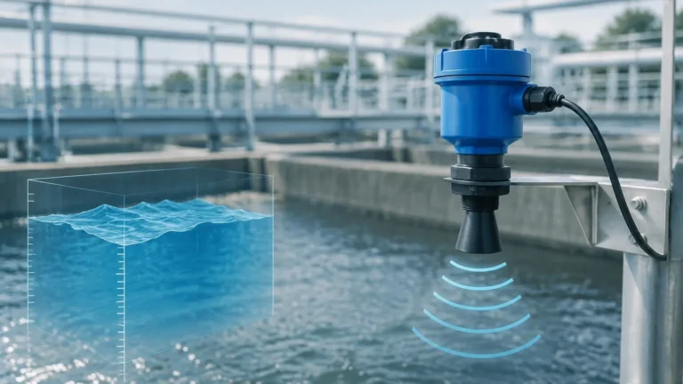
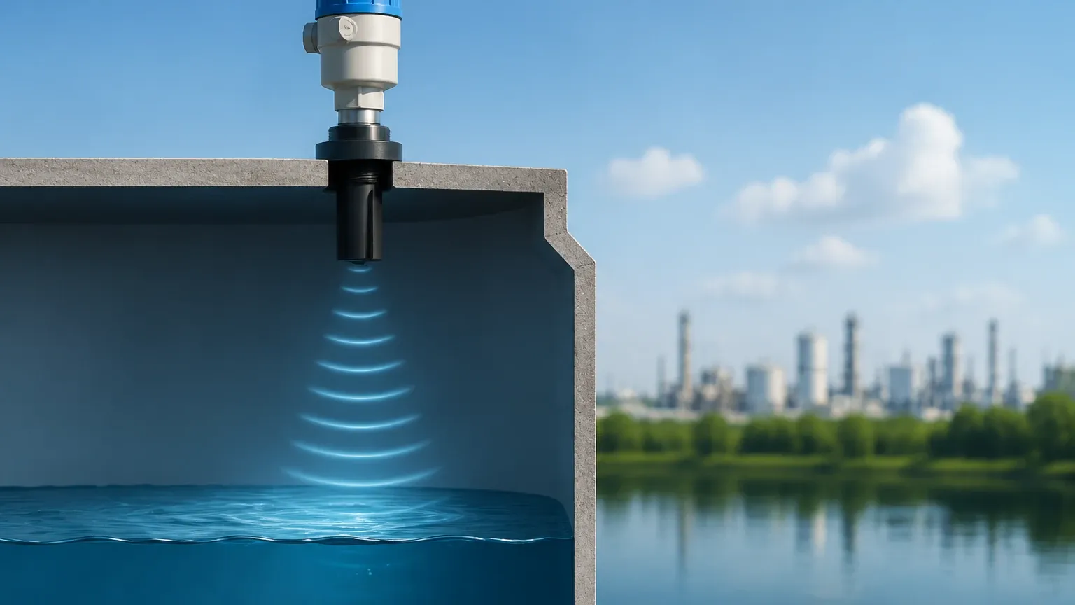
The fundamental ultrasonic level gauge working principle is based on the "Time of Flight" (ToF) measurement of sound waves. Unlike contact-based methods such as hydrostatic pressure or magnetic floats, ultrasonic sensors operate by emitting high-frequency sound pulses that travel through the air (or gas) medium to the surface of the material being measured.
The Measurement Cycle
1. Emission: The sensor's transducer contains a piezoelectric crystal. When energized by an electrical pulse, this crystal vibrates at a specific frequency (typically between 20 kHz and 200 kHz), emitting a burst of ultrasonic sound waves.
2. Propagation: These sound waves travel through the air space in the vessel toward the target material.
3. Reflection: Upon hitting the surface of the liquid or solid, a portion of the sound energy is reflected back toward the sensor as an echo.
4. Detection: The transducer receives the reflected echo and converts the mechanical energy back into an electrical signal.
5. Calculation: The internal microprocessor measures the time interval between the emission of the pulse and the reception of the echo.
The Mathematical Formula
The distance from the sensor to the material surface is calculated using the following formula:
D = (c × t) / 2
Where:
* D is the distance from the sensor to the material surface (m).
* c is the velocity of sound in the medium (m/s).
* t is the measured transit time (s).
Since the sound must travel to the surface and back, the total distance is divided by two. To determine the actual level (L) of the material in the tank, the device subtracts the measured distance (D) from the total height of the tank (H), which is programmed during commissioning: L = H – D.
Key Components of Ultrasonic Level Meters
To execute the ultrasonic level gauge working principle effectively, modern instruments consist of several critical components:
* Transducer: The "heart" of the meter, responsible for both transmitting and receiving pulses. Welk utilizes high-grade piezoelectric materials to ensure signal clarity and longevity.
* Processing Electronics: These include the signal generator, amplifier, and microprocessor. Advanced electronics use digital signal processing (DSP) to filter out noise and identify the correct echo among multiple reflections.
* Temperature Sensor: Since the speed of sound changes with air temperature, most high-quality ultrasonic level meters include an integrated temperature sensor to provide real-time compensation.
* Housing: Usually rated IP66 or IP68, the housing protects the electronics from corrosive atmospheres and moisture.
Technical Selection and Application Criteria
Selecting the right instrument requires matching the sensor's capabilities with the specific requirements of the application. For a detailed look at specific models and technical data, engineers should Review product options and application support to ensure the selected device fits the process parameters.
Selection Table: Ultrasonic Level Meter Specifications
| Feature | Standard Liquid Application | Corrosive/Chemical Application | Bulk Solid Application |
| :— | :— | :— | :— |
| Measurement Range | 0.4m to 15m (1.3ft to 49ft) | 0.4m to 10m (1.3ft to 33ft) | 0.5m to 20m (1.6ft to 65ft) |
| Transducer Material | ABS / PVC | PVDF / PTFE | Reinforced Nylon / Aluminum |
| Beam Angle | 8° to 12° | 6° to 10° | 5° to 8° (Narrower is better) |
| Output Signal | 4-20mA / HART | 4-20mA / RS485 | 4-20mA / Modbus |
| Accuracy | ±0.25% to ±0.5% of range | ±0.25% to ±0.5% of range | ±1% of range |
Critical Installation Considerations
Even the most advanced ultrasonic level meter will fail to provide accurate readings if installed incorrectly. Adhering to the following guidelines is essential for maintaining the integrity of the ultrasonic level gauge working principle.
1. The Dead Zone (Blocking Distance)
Every ultrasonic sensor has a "dead zone" or "blocking distance" directly beneath the transducer face. This is the time required for the piezoelectric crystal to stop vibrating after the transmission pulse before it can listen for the echo. If the material level enters this zone, the meter will provide an erroneous reading or lose the signal entirely. Typical dead zones range from 0.2m to 0.6m (0.6ft to 2ft) depending on the frequency.
2. Mounting Position and Orientation
* Verticality: The sensor must be mounted perfectly perpendicular to the liquid surface. A tilt of even a few degrees can cause the reflected echo to miss the transducer.
* Wall Distance: Do not mount the sensor too close to the vessel wall. The beam spreads as it travels (the beam angle), and reflections from the wall or weld seams can create "false echoes."
* Obstructions: Ensure the path of the ultrasonic beam is clear of ladders, pipes, or agitators. If obstructions are unavoidable, many Welk instruments offer "false echo suppression" software to ignore these static reflections.
3. Turbulence and Foam
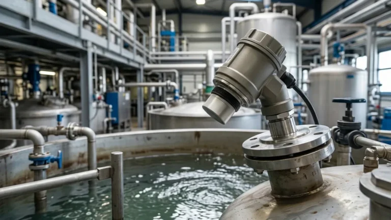
In water treatment or chemical mixing, surface turbulence and foam are common. Turbulence scatters the sound wave, weakening the return echo. Foam is particularly challenging because it absorbs the sound energy rather than reflecting it. In cases of heavy foam, ultrasonic technology may not be suitable, and a radar or hydrostatic transmitter might be recommended.
Environmental Factors and Limitations
While highly versatile, the ultrasonic level gauge working principle is subject to certain physical limitations that must be understood during the engineering phase.
* Temperature Gradients: Rapid changes in temperature or significant temperature layers in the air space can refract the sound wave, leading to inaccuracies. Integrated temperature compensation helps, but it measures temperature at the sensor, not necessarily throughout the entire tank height.
* Pressure: Ultrasonic meters are generally designed for atmospheric or near-atmospheric pressure. High pressure increases the density of the gas, which can affect the speed of sound and signal attenuation.
* Vacuum: Sound waves cannot travel in a vacuum. Therefore, ultrasonic meters cannot be used in full vacuum applications.
* Dust and Vapor: Heavy dust in solid silos or dense steam/vapors in liquid tanks can attenuate the signal. For these environments, selecting a sensor with a higher power output or a lower frequency is often necessary.
Maintenance and Troubleshooting
Ultrasonic level meters are valued for their low maintenance requirements due to their non-contact nature. However, periodic checks are recommended:
1. Transducer Face Cleaning: In some applications, condensation or dust can build up on the transducer face. A gentle wipe with a soft cloth is usually sufficient.
2. Signal Strength Monitoring: Most modern meters provide a signal-to-noise ratio or echo strength indicator. A declining signal strength may indicate a build-up on the sensor or a change in process conditions (e.g., increased foam).
3. Recalibration: While the electronics do not drift, changes in the gas composition (e.g., a high concentration of CO2 instead of air) will change the speed of sound and require a recalibration of the "c" constant.
Frequently Asked Questions (FAQs)
Q: Can ultrasonic level meters be used for solids?
A: Yes, but with considerations. Solids like grain, sand, or plastic pellets have an angle of repose that can scatter the signal. A more powerful transducer with a narrow beam angle is typically required for solid applications compared to liquids.
Q: How does wind affect outdoor ultrasonic level measurement?
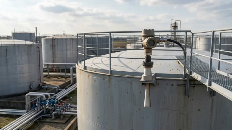
A: Strong winds can "blow" the sound wave away from the vertical path, potentially causing a loss of signal. In outdoor installations, using a stilling well or a protective sunshade can help stabilize readings.
Q: What is the difference between a 2-wire and 4-wire ultrasonic meter?
A: A 2-wire meter is loop-powered, meaning the power and the 4-20mA signal share the same pair of wires. These are energy-efficient but have lower processing power. A 4-wire meter has separate power and signal wires, allowing for higher-power pulses and better performance in difficult environments with dust or steam.
Q: Is the speed of sound constant?
A: No. The speed of sound is primarily affected by temperature and the composition of the gas. In air at sea level, it is approximately 343 m/s (1,125 ft/s) at 20°C (68°F). Because of this variability, temperature compensation is a standard feature in professional-grade Ultrasonic Level Meters.
By understanding the ultrasonic level gauge working principle and the environmental factors that influence it, engineers can implement reliable level measurement solutions that minimize downtime and maximize process accuracy. Whether managing a municipal wastewater facility or a complex chemical storage farm, the correct application of ultrasonic technology remains a cornerstone of modern industrial instrumentation.