Ultrasonic Level Meter Working Principle
Ultrasonic Level Meter Working Principle: A Comprehensive Engineering Guide
In the realm of industrial process control, accurate level measurement is a cornerstone of operational efficiency, safety, and inventory management. Among the various technologies available, non-contact ultrasonic measurement has emerged as a preferred solution for a wide range of applications, from wastewater treatment to chemical storage. Understanding the ultrasonic level meter working principle is essential for engineers and technicians tasked with selecting, installing, and maintaining these instruments to ensure long-term reliability.
This guide provides a technical deep dive into the physics of ultrasound in level sensing, the components that make these systems function, and the practical considerations required for successful field implementation.
The Physics of Ultrasound
Before examining the specific mechanics of the instrument, it is necessary to understand the nature of the medium: sound. Ultrasound refers to sound waves with frequencies higher than the upper audible limit of human hearing, typically above 20 kHz. Industrial Ultrasonic Level Meters generally operate in the range of 20 kHz to 200 kHz.
Sound waves are mechanical longitudinal waves that require a medium (liquid, solid, or gas) to propagate. In the context of level measurement, the medium is usually the air or vapor space above the material being measured. The speed at which these waves travel—the speed of sound—is a critical variable in the measurement equation.
The Ultrasonic Level Meter Working Principle: Time-of-Flight (ToF)
The fundamental ultrasonic level meter working principle is based on the "Time-of-Flight" (ToF) measurement method. The process can be broken down into four distinct stages:
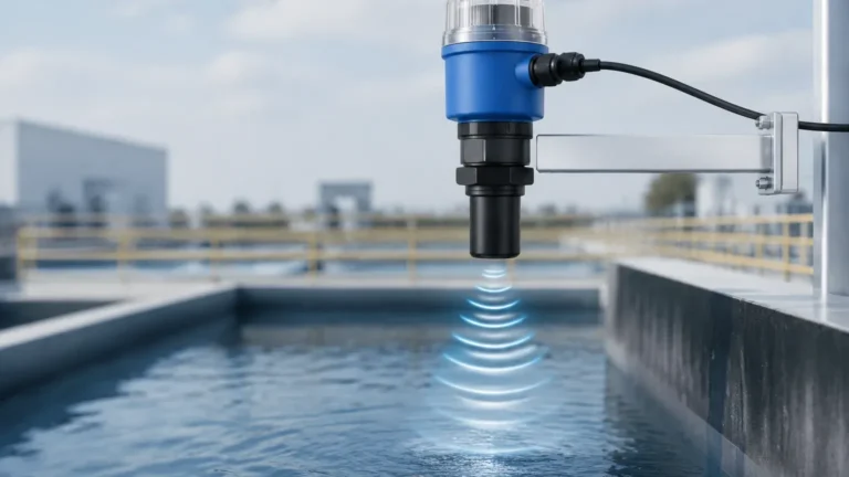
1. Emission: The instrument’s transducer contains a piezoelectric crystal. When excited by an electrical pulse, this crystal vibrates, converting electrical energy into mechanical energy in the form of an ultrasonic pulse.
2. Propagation: This pulse travels through the air toward the surface of the target material (liquid or solid).
3. Reflection: Upon reaching the surface, a portion of the sound energy is reflected back toward the sensor. This reflection occurs because of the difference in acoustic impedance between the air and the material surface.
4. Detection: The transducer receives the reflected echo and converts the mechanical vibration back into an electrical signal. The onboard electronics then calculate the time elapsed between the emission and the reception of the pulse.
The Mathematical Formula
The distance ($D$) from the sensor face to the material surface is calculated using the following formula:
D = (c × t) / 2
Where:
* D = Distance to the material surface (meters).
* c = Speed of sound in the medium (approximately 344 m/s in air at 20°C).
* t = Time-of-Flight (the total time for the pulse to travel to the surface and back).
The result is divided by two because the time measured represents a round trip.
To determine the actual Level (L) of the material in a tank, the instrument subtracts the measured distance (D) from the total Tank Height (H), which is programmed into the device during commissioning:
L = H – D
Key Components of an Ultrasonic Level System
An ultrasonic level meter is more than just a transducer; it is a sophisticated signal-processing unit. The primary components include:
1. The Transducer
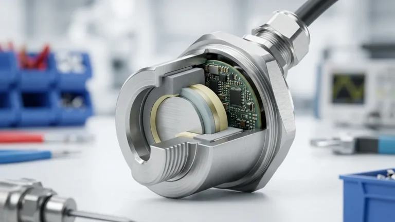
The transducer is the "heart" of the meter. It typically utilizes piezoelectric ceramics. The design of the transducer determines the beam angle—the spread of the ultrasonic pulse. A narrower beam angle is generally preferred as it helps avoid interference from tank internal structures like ladders or agitators.
2. Signal Processing Electronics
Modern instruments use advanced algorithms to distinguish the "true" echo from "false" echoes caused by noise, foam, or tank obstructions. This is often referred to as "Echo Mapping" or "False Echo Suppression."
3. Temperature Sensor
As the speed of sound varies with temperature (increasing by approximately 0.6 m/s for every degree Celsius increase), an integrated temperature sensor is vital. It allows the meter to perform real-time compensation, maintaining accuracy despite environmental fluctuations.
Selection Criteria for Industrial Applications
Choosing the right ultrasonic level meter requires an analysis of the process environment. The following table outlines the primary considerations for selection:
| Feature | Integrated Type | Split Type |
| :— | :— | :— |
| Configuration | Sensor and electronics in one housing. | Sensor and remote display unit connected by cable. |
| Best For | Standard tanks, outdoor sumps, easy access. | High-temperature tanks, hazardous areas, remote monitoring. |
| Installation | Simplified wiring, lower cost. | Allows display to be mounted at eye level or in a control room. |
| Protection | Typically IP65 to IP68. | Sensor can be high-protection; controller kept in safe zone. |
| Power Options | 2-wire (loop-powered) or 4-wire. | Usually 4-wire (AC or DC). |
Installation Guidelines and Best Practices
Even the most advanced Ultrasonic Level Meters will fail if installed incorrectly. To ensure the ultrasonic level meter working principle functions as intended, follow these engineering standards:
1. Respect the Dead Zone (Blocking Distance)
Every ultrasonic sensor has a "Dead Zone" directly beneath the transducer face (typically 0.2m to 0.5m, depending on the frequency). In this zone, the transducer cannot switch from "transmit" to "receive" mode fast enough to capture the echo. The maximum liquid level must never enter this dead zone, or the meter will provide erratic readings or a "lost echo" error.
2. Positioning and Orientation
* Avoid the Center: In cylindrical tanks with domed tops, do not mount the sensor in the exact center. This can create a "parabolic" effect, focusing multiple reflections back to the sensor and causing signal interference.
* 1/3 Radius Rule: A common rule of thumb is to mount the sensor at approximately 1/3 of the tank radius from the wall.
* Perpendicularity: The sensor face must be perfectly parallel to the liquid surface. A tilt of even a few degrees can cause the reflected signal to miss the transducer entirely.
* Avoid the Fill Stream: Never install the sensor directly above the point where material enters the tank. The turbulence and falling material will obstruct the signal.
3. Mounting Nozzles
If the sensor is mounted on a nozzle (standpipe), the nozzle must be short and wide enough to prevent the ultrasonic beam from hitting the nozzle walls, which creates false echoes.

Factors Affecting Accuracy and Limitations
While highly versatile, the ultrasonic level meter working principle has specific physical boundaries:
* Pressure Extremes: Ultrasonic meters are generally designed for atmospheric or near-atmospheric pressure. High pressure increases the density of the air, significantly altering the speed of sound and potentially dampening the signal.
* Heavy Foam: Thick, protein-based foam can absorb the ultrasonic pulse rather than reflecting it, leading to signal loss. For light foam, a higher-power transducer may compensate.
* Vacuum: Sound cannot travel in a vacuum. Therefore, ultrasonic technology is unsuitable for vacuum tanks.
* Vapor and Gas Layers: If the tank contains a gas other than air (e.g., Nitrogen or Carbon Dioxide), the speed of sound will differ from the standard calibration. In such cases, the meter must be calibrated for the specific gas constant.
* Dust and Turbulence: Heavy dust in solid silos or extreme turbulence in liquid tanks can scatter the signal. Using a sensor with a lower frequency (which has more power) can often mitigate these effects.
Comparison: Ultrasonic vs. Radar
Engineers often weigh ultrasonic technology against Radar (FMCW or Pulsed). While Radar is unaffected by temperature and vacuum, ultrasonic meters remain the preferred choice for many B2B applications due to their cost-effectiveness—often 30% to 50% less expensive than radar—and their excellent performance in water-based applications where the dielectric constant is high.
Frequently Asked Questions (FAQs)
Q: Can ultrasonic level meters measure solids?
A: Yes, but with caveats. Solids like grain or plastic pellets have an "angle of repose" that can deflect the signal away from the sensor. Lower frequency sensors and specialized mounting are usually required.
Q: How does wind affect outdoor installations?
A: Strong wind can "blow" the ultrasonic pulse away, especially over long distances (e.g., 10+ meters). For outdoor sumps or rivers, a protective stilling well or a higher-power sensor is recommended.
Q: What is the typical accuracy of an ultrasonic level meter?
A: Most industrial-grade meters offer an accuracy of ±0.25% to ±0.5% of the measured range, provided temperature compensation is active and the installation is correct.
Q: Does the color or transparency of the liquid matter?
A: No. Unlike optical sensors, the ultrasonic level meter working principle relies on sound reflection, so the color, opacity, or transparency of the liquid has no impact on measurement.
Conclusion
Modern ultrasonic level meters represent a mature, reliable, and cost-efficient technology for industrial level monitoring. By adhering to the fundamental ultrasonic level meter working principle—calculating the time-of-flight of sound waves—these instruments provide non-contact measurement that reduces maintenance requirements compared to mechanical alternatives.
Success in the field depends on a thorough understanding of the environmental factors—temperature, pressure, and tank geometry—that influence sound propagation. When selected and installed according to engineering best practices, ultrasonic meters provide the precision necessary for advanced process automation and inventory control. For those seeking specific hardware solutions, exploring a range of Ultrasonic Level Meters tailored to industrial needs is the recommended next step in the procurement process.