Ultrasonic Volume Measurement
A Comprehensive Guide to Ultrasonic Volume Measurement in Industrial Applications
In industrial process control and inventory management, knowing the height of a liquid is often only the first step. For most operators, the critical metric is volume—the actual amount of product stored in a vessel. Ultrasonic volume measurement has emerged as a preferred non-contact solution for these requirements, offering a balance of accuracy, reliability, and cost-effectiveness. By utilizing advanced Ultrasonic Level Meters, engineers can convert precise distance readings into real-time volume data for tanks of various geometries.
This article provides a technical overview of how ultrasonic technology facilitates volume measurement, the mathematical principles involved, and the practical considerations for selecting and installing these instruments in a B2B environment.
Understanding the Measurement Principle
Before implementing a volume measurement system, it is essential to understand the underlying physics of ultrasonic technology. Ultrasonic sensors operate on the "Time-of-Flight" (ToF) principle.
Time-of-Flight (ToF) Mechanism
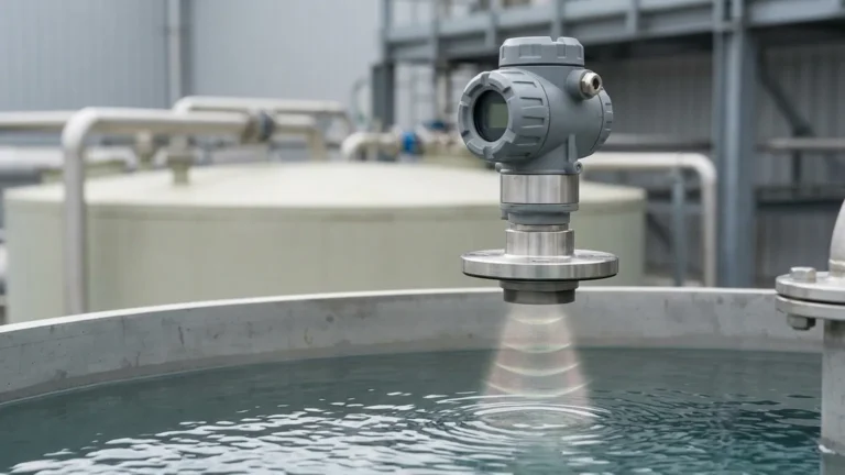
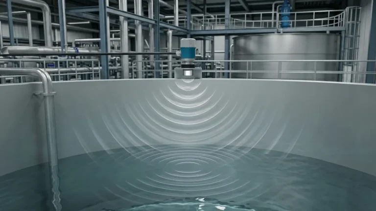
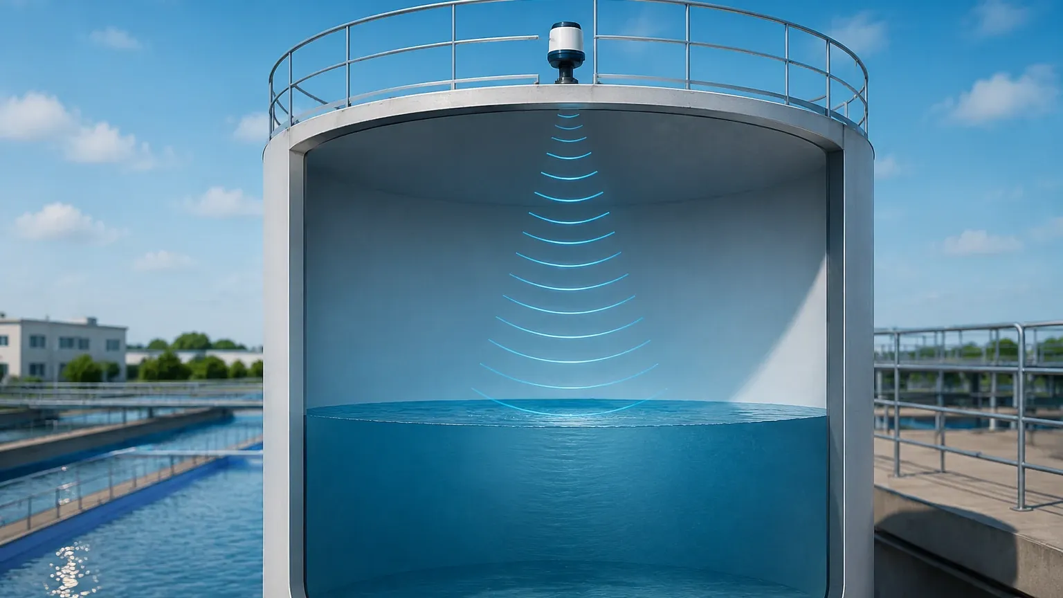
The sensor, mounted at the top of a vessel, emits a high-frequency acoustic pulse (typically between 20 kHz and 200 kHz). This pulse travels through the air space in the tank, hits the surface of the medium, and reflects back to the sensor's transducer. The instrument measures the time interval ($t$) between the emission and the reception of the echo.
Using the known speed of sound in air ($v$), the distance ($D$) from the sensor to the material surface is calculated as:
$$D = \frac{v \times t}{2}$$
From Distance to Level
To determine the level ($L$) of the material, the distance ($D$) is subtracted from the total tank height ($H$), which is a user-defined parameter during commissioning:
$$L = H – D$$
From Level to Volume
This is where ultrasonic volume measurement diverges from simple level detection. The instrument’s internal processor applies a mathematical function or a look-up table to convert the level ($L$) into volume ($V$). This conversion depends entirely on the vessel's internal geometry. In modern industrial level meters, these calculations are performed internally, allowing the device to output volume directly in liters, cubic meters, or gallons.
Volume Calculation for Common Tank Geometries
The complexity of volume measurement depends on whether the relationship between level and volume is linear or non-linear.
1. Vertical Cylindrical and Rectangular Tanks
In these vessels, the cross-sectional area remains constant regardless of the liquid height. The relationship is linear:
* Rectangular: $V = Length \times Width \times L$
* Vertical Cylinder: $V = \pi \times r^2 \times L$
For these shapes, a simple scaling factor is applied to the level reading.
2. Horizontal Cylindrical Tanks
Horizontal tanks are common in oil and gas and chemical storage. Unlike vertical tanks, the volume increase is non-linear. As the liquid rises, the cross-sectional area of the liquid surface changes. The calculation requires a more complex geometric formula involving the radius of the tank and the segment area of the circle.
3. Spherical and Dished-Bottom Tanks
Vessels with conical, spherical, or dished bottoms are frequently used to facilitate drainage. In these cases, the volume per unit of height changes significantly at the bottom of the tank. Professional Ultrasonic Level Meters allow engineers to input "strapping tables" (or 20-point linearization tables) to map specific level readings to exact volumes, ensuring accuracy even in irregularly shaped vessels.
Selection Criteria for Ultrasonic Volume Measurement
Choosing the right instrument requires an analysis of the application environment and the material being measured. Welk provides a range of sensors designed for diverse industrial needs.
Selection Table: Ultrasonic Sensor Specifications
| Feature | Standard Liquid Storage | Corrosive/Chemical Tanks | Open Channel Flow | Large Scale Silos |
| :— | :— | :— | :— | :— |
| Measuring Range | 0.3m – 15m | 0.3m – 10m | 0.2m – 5m | Up to 30m |
| Transducer Material | ABS / Nylon | PTFE / PVDF | ABS / Stainless Steel | Reinforced Polymer |
| Accuracy | 0.25% – 0.5% of range | 0.25% of range | ±1mm to 2mm | 0.5% of range |
| Output Signal | 4-20mA, RS485 | 4-20mA, HART | 4-20mA, Modbus | 4-20mA, HART |
| Pressure Limit | 0.3 MPa | 0.2 MPa | Atmospheric | 0.1 MPa |
Key Considerations
1. Chemical Compatibility: For aggressive acids or bases, sensors with PVDF or PTFE-faced transducers are mandatory to prevent corrosion.
2. Beam Angle: Ultrasonic pulses spread in a cone shape (typically 5° to 12°). If the beam is too wide, it may hit internal tank structures like ladders or agitators, resulting in false echoes.
3. Temperature Compensation: The speed of sound varies with air temperature (approx. 0.6 m/s per degree Celsius). Ensure the selected meter has an integrated temperature sensor for automatic compensation.
Installation Guidelines for Accuracy
Proper installation is the most critical factor in achieving reliable volume data. Even the most advanced ultrasonic volume measurement system will fail if the sensor is poorly positioned.
1. The Dead Zone (Blocking Distance)
Every ultrasonic sensor has a "dead zone" directly beneath the transducer where it cannot receive an echo. For a sensor with a 5-meter range, the dead zone might be 0.25 meters. The tank should never be filled into this zone, as the reading will become erratic.
2. Positioning and Orientation
* Avoid the Center: In cylindrical tanks with domed tops, mounting the sensor in the exact center can create a "parabolic mirror" effect, where multiple echoes interfere with the primary signal. Mount the sensor at 1/2 or 1/3 of the radius from the wall.
* Perpendicularity: The sensor must be installed perfectly perpendicular to the liquid surface. A tilt of even a few degrees can cause the reflected signal to miss the transducer.
* Obstruction Clearance: Ensure the "signal cone" is clear of fill pipes, cooling coils, or internal braces.
3. Turbulence and Foam
Heavy turbulence can scatter the ultrasonic signal, while thick foam can absorb it entirely. In such cases, using a stilling well (a vertical pipe that acts as a guide for the sound wave) can stabilize the liquid surface and improve measurement reliability.
Limitations and Environmental Challenges
While ultrasonic technology is versatile, it is not a "one-size-fits-all" solution. Engineers must be aware of the following limitations:
* Vacuum Conditions: Sound waves require a medium (air or gas) to travel. Ultrasonic meters cannot function in a vacuum.
* High Pressure: High-pressure environments change the density of the gas space, which significantly alters the speed of sound beyond what standard temperature compensation can handle.
* Heavy Dust or Steam: Dense dust (in powder silos) or heavy steam (in hot water tanks) can attenuate the acoustic pulse, reducing the effective range of the sensor.
* Surface Foam: Light, airy foam often absorbs the ultrasonic pulse, leading to a "Loss of Echo" error. For applications with persistent heavy foam, radar level technology may be a more suitable alternative.
Practical Applications in Industry
Ultrasonic volume measurement is widely utilized across several sectors due to its non-contact nature, which prevents contamination and reduces maintenance.
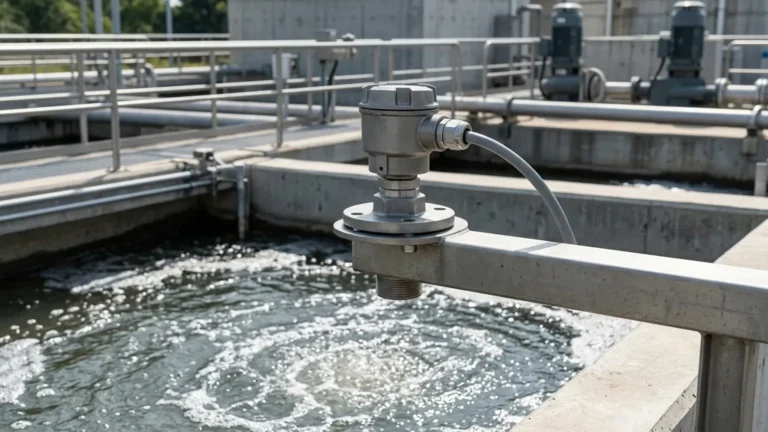
* Water and Wastewater: Measuring the volume of chemicals (like alum or chlorine) in storage tanks and monitoring flow rates in open channels using flumes and weirs.
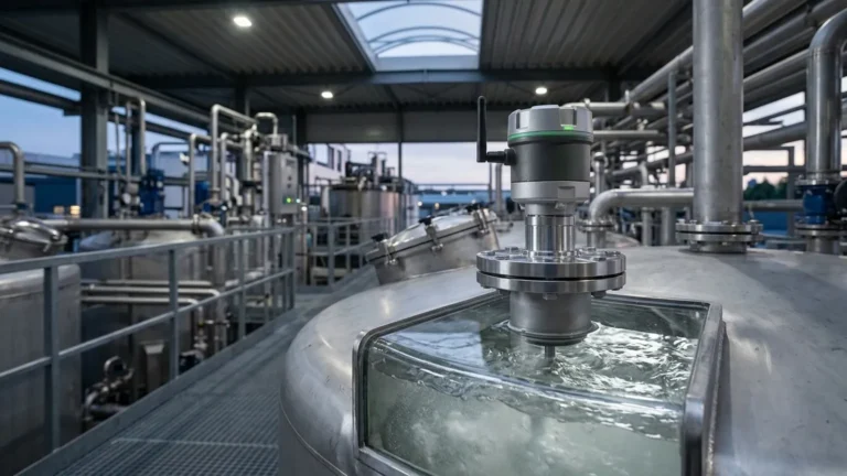
* Food and Beverage: Inventory management of juices, oils, and syrups in stainless steel vessels where hygiene is paramount.
* Chemical Processing: Monitoring the volume of reagents in plastic or glass-lined tanks without penetrating the vessel's integrity.
Frequently Asked Questions (FAQ)
Q: Can ultrasonic sensors measure the volume of solids?
A: Yes, but with caveats. Solids like grain or plastic pellets do not form a flat surface; they form a "cone of repose." This can cause the signal to scatter. Sensors for solids typically require higher power and specialized algorithms to average the uneven surface for a volume estimate.
Q: How do I handle tanks with irregular shapes that don't have a formula?
A: Most professional Ultrasonic Level Meters support a multi-point linearization table. You can manually input a series of points (e.g., at 10cm the volume is 50L, at 20cm it is 120L). The device interpolates between these points to provide a continuous volume output.
Q: Does the material of the tank affect the measurement?
A: Generally, no. Since the measurement is non-contact and reflects off the liquid surface, the tank material (metal, plastic, concrete) does not affect the ultrasonic pulse. However, the tank wall can reflect the signal if the sensor is mounted too close to it.
Q: Is recalibration required often?
A: Ultrasonic sensors are solid-state and do not have moving parts, so they do not suffer from mechanical wear. Recalibration is usually only necessary if the gas composition in the tank changes (e.g., switching from air to Nitrogen), as this changes the speed of sound.
Conclusion
Implementing ultrasonic volume measurement provides industrial facilities with a high degree of visibility into their inventory and process efficiency. By understanding the geometric requirements of the vessel and the environmental constraints of the application, engineers can deploy Ultrasonic Level Meters that deliver precise, maintenance-free data for years. As a professional manufacturer, Welk continues to provide robust solutions that bridge the gap between simple level detection and sophisticated volume management.