Ultrasonic Level Sensor for Water Tank
Ultrasonic Level Sensor for Water Tank: A Comprehensive Engineering Guide
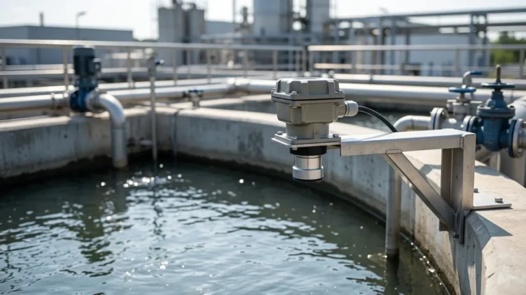
In industrial water management and process automation, accurate level monitoring is fundamental to operational efficiency, safety, and resource conservation. Among the various technologies available, the ultrasonic level sensor for water tank applications has emerged as a preferred solution due to its non-contact nature and versatility. This guide provides a detailed technical overview of how these instruments function, how to select the correct model, and the critical installation parameters required for reliable performance.
Understanding the Measurement Principle
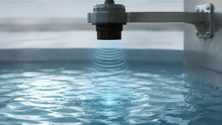
Ultrasonic level measurement is based on the "Time-of-Flight" (ToF) principle. The sensor, typically mounted at the top of the water tank, contains a piezoelectric transducer that converts electrical energy into mechanical vibrations, emitting high-frequency ultrasonic sound pulses. These pulses travel through the air gap between the sensor and the water surface.
When the sound waves hit the surface of the water, they are reflected back toward the sensor as an echo. The transducer then acts as a receiver, converting the returning sound energy back into an electrical signal. The internal electronics of the device calculate the distance based on the following formula:
Distance = (Speed of Sound × Time Delay) / 2
Since the speed of sound in air is approximately 344 m/s (at 20°C), the device can determine the distance to the water level with high precision. By subtracting this distance from the total tank height (the "zero point"), the sensor calculates the actual level of the liquid. For industrial-grade Ultrasonic Level Meters, integrated temperature sensors are essential. Because the speed of sound changes by roughly 0.17% per degree Celsius, onboard temperature compensation ensures that the measurement remains accurate despite fluctuations in the tank's headspace temperature.
Why Choose an Ultrasonic Level Sensor for Water Tank Monitoring?
Selecting an ultrasonic level sensor for water tank applications offers several distinct advantages over contact-based methods like float switches or pressure transmitters:
1. Non-Contact Measurement: The sensor never touches the water. This is critical for potable water applications where hygiene is paramount, or in wastewater applications where debris and chemicals could corrode or clog mechanical sensors.
2. Low Maintenance: With no moving parts to wear out or mechanical components to clean, ultrasonic sensors significantly reduce the total cost of ownership over the life of the instrument.
3. High Accuracy: Modern digital signal processing allows these sensors to achieve accuracies of ±0.25% to ±0.5% of the measured range, providing reliable data for inventory management and pump control.
4. Versatility: These sensors can be used in various tank materials, including plastic (HDPE/PP), concrete, and stainless steel, and are suitable for both indoor and outdoor environments.
Technical Selection Criteria
Choosing the right instrument requires an understanding of the specific environment of the water tank. Engineers should evaluate the following parameters before procurement:
1. Measurement Range
Water tanks vary from shallow sumps (1–2 meters) to large industrial reservoirs (up to 30 meters). Ensure the sensor’s maximum range exceeds the tank height, but also pay close attention to the "Dead Zone" (or blocking distance). This is the area immediately below the sensor (typically 0.25m to 0.6m) where it cannot measure. If the water level enters this zone, the reading will become erratic.
2. Beam Angle
The ultrasonic pulse spreads out in a cone shape. A narrower beam angle (e.g., 5° to 10°) is preferable for narrow tanks or tanks with internal obstructions like ladders, pipes, or reinforcement struts. A wide beam angle may cause the sensor to detect the tank wall or internal structures instead of the water surface.
3. Output and Communication
For integration into SCADA or PLC systems, standard outputs include 4-20mA (analog) and RS485 Modbus (digital). Some advanced models also support HART protocol for remote configuration and diagnostics.
4. Environmental Conditions
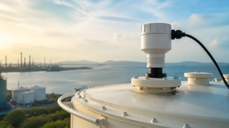
If the tank is outdoors, the sensor housing should be UV-resistant and rated at least IP66 or IP67. For corrosive environments, such as chemical-treated water or brine tanks, the wetted parts (transducer face) should be made of PVDF or PTFE instead of standard ABS plastic.
Practical Selection Table
| Feature | Small Storage Tank (Potable) | Industrial Wastewater Sump | Large Outdoor Reservoir |
| :— | :— | :— | :— |
| Measuring Range | 0.4m – 5m | 0.5m – 10m | 0.8m – 30m |
| Transducer Material | ABS or PP | PVDF (Corrosion resistant) | Reinforced ABS |
| Beam Angle | 10° – 12° | 8° – 10° | 5° – 8° |
| Accuracy | ±3mm | ±0.25% FS | ±0.25% FS |
| Protection Rating | IP66 | IP67 / IP68 | IP67 / NEMA 4X |
| Typical Output | 4-20mA | 4-20mA + Modbus | RS485 / GPRS |
Installation Considerations for Water Tanks
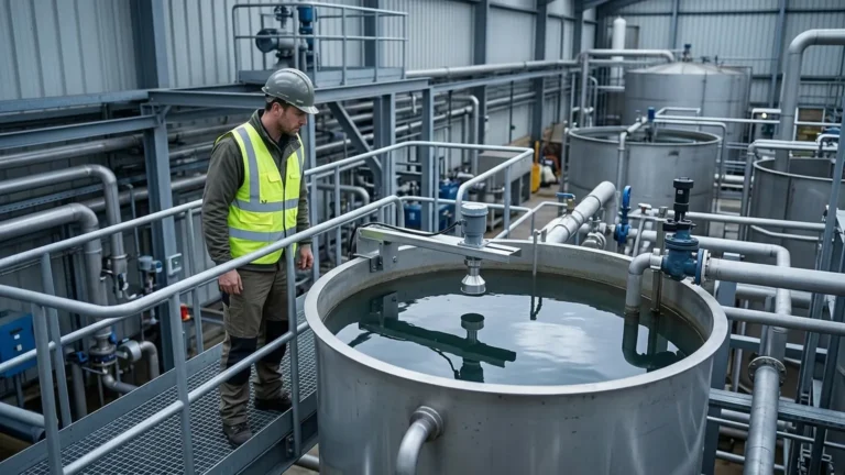
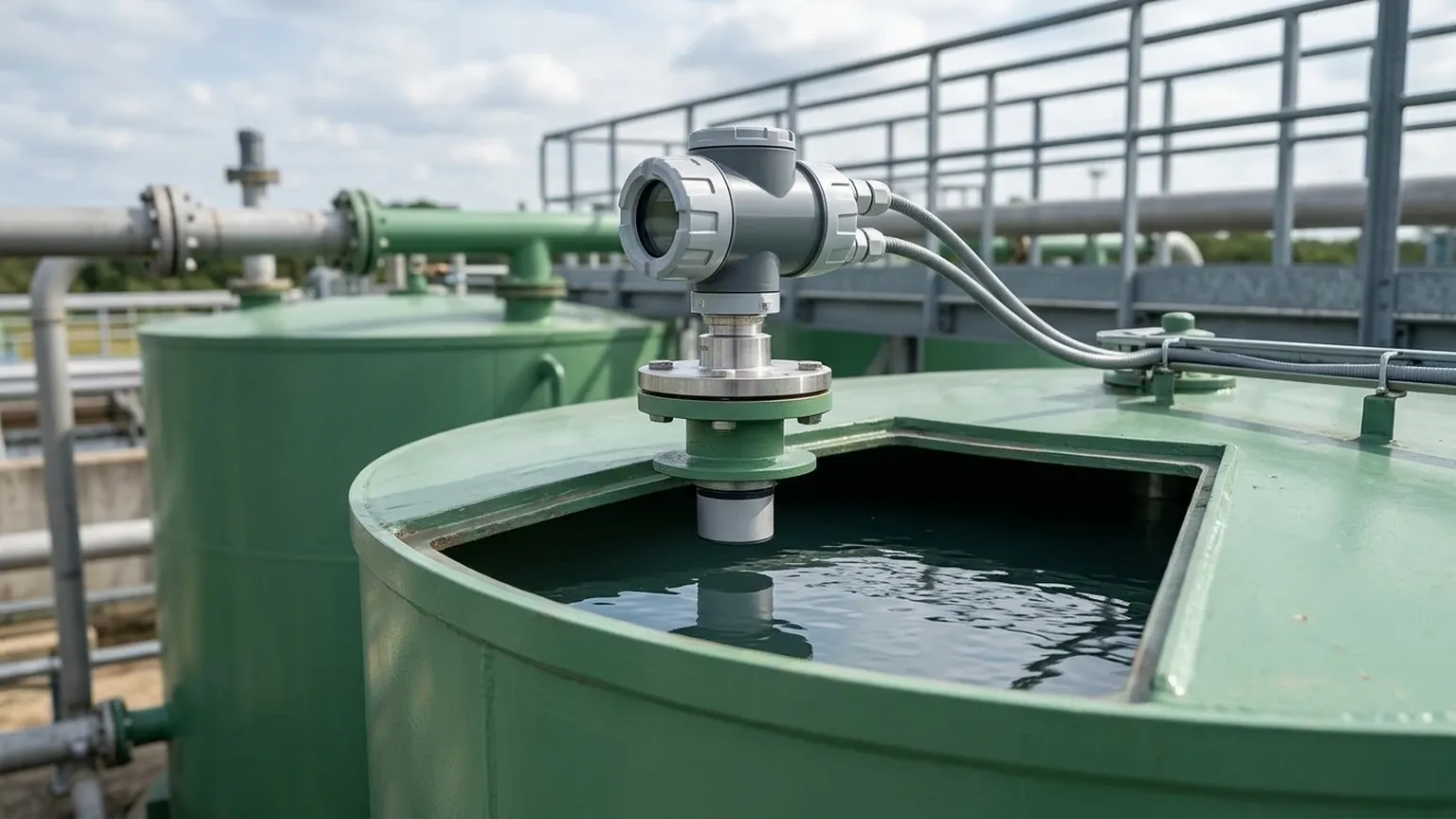
Proper installation is the most critical factor in ensuring the reliability of an ultrasonic level sensor for water tank systems. Even the most advanced sensor will fail if positioned incorrectly.
Mounting Position
* Avoid the Center: In tanks with a domed roof, do not mount the sensor in the exact center. The dome can act as a parabolic reflector, concentrating multiple echoes back to the sensor and causing false readings.
* Avoid the Wall: Mount the sensor at a distance from the tank wall that is at least 1/6th of the tank diameter. This prevents the ultrasonic beam from hitting the wall and returning a "false floor" signal.
* Clear Path: Ensure there are no pipes, ladders, or fill streams within the ultrasonic beam cone. If the water enters the tank from the top, the sensor must be placed away from the turbulence and splashing caused by the inlet.
Alignment
The sensor face must be perfectly parallel to the water surface. If the sensor is tilted, the ultrasonic pulse will bounce off the water at an angle and may not return to the transducer, leading to a "Loss of Echo" error.
Standpipes and Nozzles
If the sensor must be mounted on a nozzle, the nozzle should be as short and wide as possible. If the nozzle is too long or narrow, the ultrasonic pulse will bounce off the internal walls of the nozzle before reaching the tank, creating a large dead zone and signal interference.
Limitations and Challenges
While highly effective, ultrasonic technology is not a "one-size-fits-all" solution. Engineers must be aware of specific conditions that can interfere with sound wave propagation:
* Heavy Foam: Thick, dense foam on the water surface acts as an acoustic absorber. It soaks up the ultrasonic pulse instead of reflecting it, leading to signal loss. In such cases, a radar level meter or hydrostatic pressure sensor may be more appropriate.
* Extreme Turbulence: Rapidly churning water (e.g., near a high-powered agitator) can scatter the ultrasonic signal. This can often be mitigated by using a stilling well—a vertical pipe that shields the sensor from surface waves.
* Vapor and Steam: While water vapor is generally manageable, heavy steam can change the density of the air in the tank's headspace, affecting the speed of sound and causing measurement errors unless the sensor has advanced compensation algorithms.
* Vacuum or High Pressure: Ultrasonic waves require a medium (air/gas) to travel. They cannot function in a vacuum. Similarly, extremely high pressure can change the acoustic impedance of the air, though most standard water tanks are atmospheric.
Frequently Asked Questions (FAQ)
Q: Can I use an ultrasonic sensor for a tank containing chemicals for water treatment?
A: Yes, provided the transducer face is made of a chemically resistant material like PVDF. Always check the compatibility of the chemical vapors with the sensor's housing and gasket materials.
Q: How do I handle the "Dead Zone" if my tank frequently fills to the very top?
A: You can install the sensor on a mounting bracket or a short standpipe that raises the sensor above the maximum fill level. This ensures the water surface never enters the blocking distance of the device.
Q: Does the tank material (plastic vs. metal) affect the measurement?
A: No. Since the measurement is based on the reflection from the water surface, the tank material does not affect the signal. However, the internal walls of the tank should be relatively smooth to avoid stray reflections if the beam angle is wide.
Q: Is it possible to monitor water tanks remotely?
A: Absolutely. By selecting a sensor with RS485 Modbus or 4-20mA outputs, the data can be sent to a wireless gateway or a cellular RTU, allowing for real-time monitoring on mobile devices or remote control centers.
Conclusion
The implementation of a high-quality ultrasonic level sensor for water tank monitoring provides a balance of accuracy, ease of use, and long-term reliability. By understanding the acoustic principles and adhering to strict installation guidelines, facility managers can ensure precise inventory tracking and prevent costly overflows or pump dry-run scenarios. For complex industrial applications involving multiple tanks or integrated automation, consulting with a specialized manufacturer like Welk ensures that the selected Ultrasonic Level Meters are perfectly matched to the operational requirements of the site.