Ultrasonic Level Sensor Operation
Ultrasonic Level Sensor Operation: A Comprehensive Engineering Guide
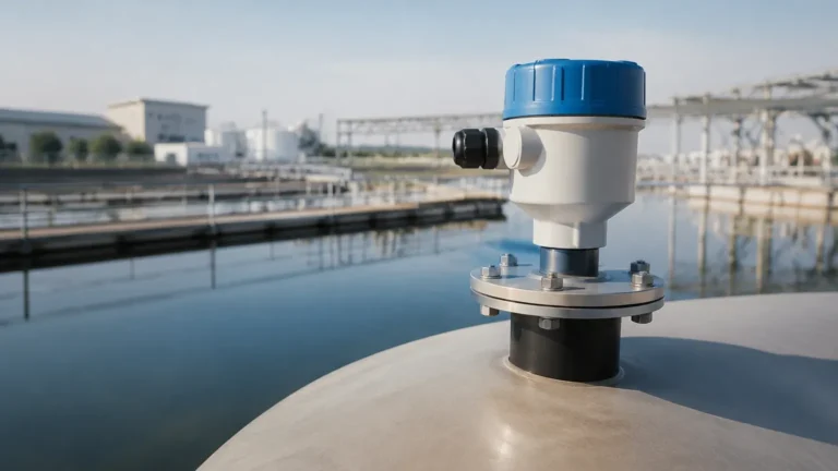
In the landscape of industrial automation, precise liquid and solid level measurement is critical for operational efficiency, safety, and inventory management. Among the various technologies available, Ultrasonic Level Meters have emerged as a preferred non-contact solution for a wide array of applications, from water treatment facilities to chemical processing plants. Understanding the intricacies of ultrasonic level sensor operation is essential for engineers and plant managers to ensure accurate data acquisition and long-term system reliability.
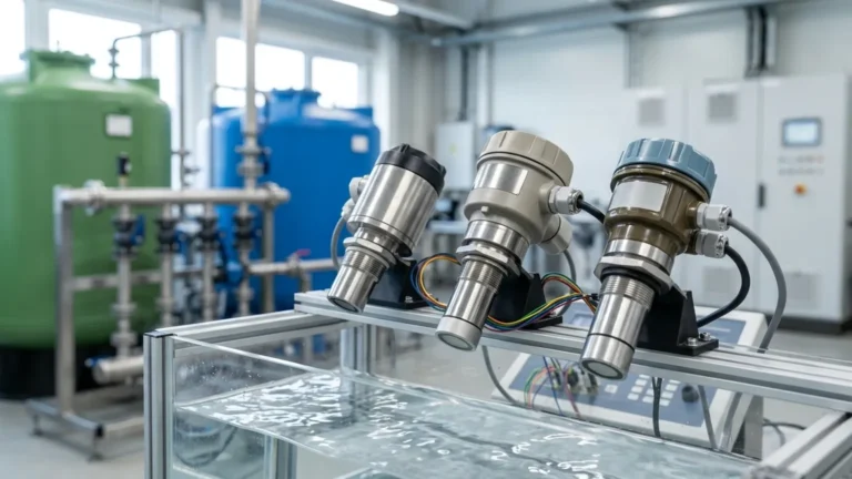
Welk, as a professional manufacturer of industrial level measurement instruments, provides advanced ultrasonic solutions designed to withstand rigorous industrial environments. This guide explores the physics, mechanical operation, and practical application of ultrasonic technology to assist in informed decision-making.
Understanding the Fundamental Principles of Ultrasonic Measurement
Ultrasonic level measurement is based on the "Time-of-Flight" (ToF) principle. This method relies on the propagation of sound waves through a medium—typically air—to determine the distance between the sensor and the surface of the material being measured.
The Speed of Sound and Distance Calculation
An ultrasonic transducer emits high-frequency sound pulses, usually in the range of 20 kHz to 200 kHz. These pulses travel through the air, strike the surface of the medium (liquid or solid), and reflect back to the transducer. The sensor acts as both a transmitter and a receiver.
The distance ($D$) from the sensor to the material surface is calculated using the following formula:
$$D = \frac{v \times t}{2}$$
Where:
* $v$ is the speed of sound in the medium (approximately 343 meters per second in air at 20°C).
* $t$ is the total time elapsed from the emission of the pulse to the reception of the echo.
Because the pulse travels to the surface and back, the total distance is divided by two to find the one-way distance. The actual level of the material in a tank is then determined by subtracting this distance ($D$) from the total height of the vessel ($H$).
The Mechanics of Ultrasonic Level Sensor Operation
The core of ultrasonic level sensor operation lies in the piezoelectric effect. Inside the sensor head, a piezoelectric crystal converts electrical energy into mechanical vibrations (sound waves) and vice versa.
1. Pulse Emission
When an electrical excitation is applied to the piezoelectric element, it vibrates at a specific frequency, creating an ultrasonic pulse. This pulse is focused into a beam by the shape of the transducer housing. The beam angle is a critical specification, as it determines the "footprint" of the signal at the target surface.
2. The "Dead Band" or Blocking Distance
Immediately after emitting a pulse, the piezoelectric crystal continues to vibrate for a microscopic duration, known as "ringing." During this time, the sensor cannot accurately process returning echoes. This creates a "Dead Band" (typically 0.2 meters to 0.6 meters depending on the frequency) directly below the sensor face where measurement is impossible. Proper installation must account for this distance to avoid false readings when a tank is full.
3. Signal Processing and Echo Analysis
Industrial environments are rarely acoustically "clean." Reflections can come from tank walls, agitators, or ladders. Modern Ultrasonic Level Meters utilize sophisticated Digital Signal Processing (DSP) algorithms to filter out these false echoes. The sensor analyzes the amplitude, shape, and timing of returning signals to identify the "true" echo from the material surface.
4. Temperature Compensation
The speed of sound is not constant; it varies significantly with temperature. In air, the speed of sound changes by approximately 0.6 meters per second for every degree Celsius change. To maintain accuracy, Welk ultrasonic sensors include an integrated temperature sensor to provide real-time compensation, ensuring the calculated distance remains precise despite environmental fluctuations.
Key Evaluation Criteria for Industrial Applications
When selecting an ultrasonic sensor, engineers must evaluate several technical parameters to ensure the device matches the application requirements.
* Measurement Range: Sensors are rated for specific distances. Higher frequency sensors (e.g., 80 kHz) offer higher resolution but shorter ranges, while lower frequency sensors (e.g., 20 kHz) can measure up to 30 or 40 meters.
* Beam Angle: A narrower beam angle (typically 5° to 12°) is preferable for tall, narrow tanks or vessels with internal obstructions, as it minimizes the risk of hitting the tank walls.
* Output Signal: Standard industrial outputs include 4-20mA analog signals, often with HART protocol, or digital communications like RS485 (Modbus).
* Housing Material: For corrosive environments, PVDF or PTFE-coated transducers are necessary to prevent chemical degradation.
Practical Selection and Specification Table
The following table provides a general comparison of ultrasonic sensor specifications based on common industrial needs:
| Application Type | Typical Range | Frequency | Recommended Housing | Key Feature |
| :— | :— | :— | :— | :— |
| Small Chemical Tank | 0.25m – 5m | 60-80 kHz | PVDF / Plastic | High Chemical Resistance |
| Water Reservoir | 0.5m – 15m | 40 kHz | ABS / Aluminum | Weatherproof (IP68) |
| Large Grain Silo | 1m – 30m | 20 kHz | Reinforced Aluminum | High Power for Dust Penetration |
| Open Channel Flow | 0.2m – 3m | 75 kHz | Plastic | High Accuracy / DSP Logic |

Installation Considerations for Optimal Performance
Correct installation is the most significant factor in successful ultrasonic level sensor operation. Even the most advanced sensor will fail if positioned incorrectly.
Positioning and Alignment
* Perpendicularity: The sensor face must be mounted perfectly parallel to the liquid surface. A tilt of even a few degrees can cause the reflected signal to bounce away from the transducer, resulting in signal loss.
* Avoid the Fill Stream: Never mount the sensor directly above the point where material enters the tank. The turbulence and falling material will interfere with the ultrasonic pulse.
* Wall Clearance: Maintain a distance from the tank wall to avoid "ghost echoes." A general rule is to keep the sensor at least 200mm away from the wall for every 1 meter of depth.
Nozzle Geometry
If mounting the sensor on a nozzle or standpipe, the inner diameter of the pipe must be smooth, and the sensor face should ideally extend slightly beyond the bottom of the nozzle. If the sensor is recessed too far, the pulse may reflect off the nozzle edges, creating a permanent false high-level reading.
Environmental Limitations and Signal Interference
While ultrasonic technology is versatile, it has physical limitations that must be understood during the engineering phase.
1. Vacuum Conditions: Sound requires a medium to travel. Therefore, ultrasonic sensors cannot operate in a vacuum.
2. Heavy Foam: Thick, dense foam on a liquid surface acts as an acoustic absorber. In such cases, the pulse is absorbed rather than reflected, leading to a "Loss of Echo" error. For foamy applications, a radar level meter or a magnetic level gauge may be more appropriate.
3. High Pressure: Changes in pressure alter the density of the air, which in turn affects the speed of sound. While many sensors can compensate for this, extreme high-pressure applications (above 3 bar) often require specialized calibration.
4. Vapor and Dust: Heavy steam or extremely dense dust can scatter the ultrasonic signal. While Welk sensors use high-gain transducers to penetrate moderate dust, extreme conditions may require lower-frequency, high-power units.
Maintenance and Troubleshooting
Ultrasonic sensors are generally low-maintenance because they have no moving parts and do not contact the medium. However, periodic checks are recommended:
* Transducer Face Cleaning: In applications with splashing or condensation, buildup can occur on the sensor face. Wipe the face with a soft cloth and mild detergent; avoid abrasive tools that could damage the piezoelectric surface.
* Check for Signal Loss: If the sensor intermittently reports "Loss of Echo," check for increased turbulence, foam, or changes in the chemical composition of the air (which affects the speed of sound).
* Verify Temperature Compensation: If readings drift during the day as the sun hits the tank, ensure the integrated temperature sensor is not being shielded or influenced by external heat sources unrelated to the process.
Frequently Asked Questions (FAQs)
Q: Can ultrasonic sensors measure solids like sand or plastic pellets?
A: Yes, but with caveats. Solids do not reflect sound as uniformly as liquids. The "angle of repose" (the slope of the pile) can deflect the signal. For solids, it is recommended to use a sensor with a higher power output and a more robust signal processing algorithm.
Q: How does wind affect ultrasonic level sensor operation in open-air tanks?
A: Strong winds can "blow" the ultrasonic pulse away, causing signal instability. In outdoor reservoirs, using a stilling well or a protective sunshade/windbreak can help stabilize readings.
Q: What is the difference between an ultrasonic transmitter and an ultrasonic switch?
A: An ultrasonic transmitter (or meter) provides a continuous measurement of the level (e.g., 0-100%), whereas an ultrasonic switch only detects when the material reaches a specific point (Point Level Detection) to trigger an alarm or pump.
Q: Is it possible to use ultrasonic sensors in hazardous areas?
A: Yes. Welk offers Ultrasonic Level Meters with Intrinsic Safety (Ex ia) or Flameproof (Ex d) certifications for use in explosive atmospheres common in the oil and gas or chemical industries.
By adhering to these operational principles and installation guidelines, industrial operators can leverage ultrasonic technology to achieve precise, non-contact level monitoring across a vast range of process conditions.