1 Ultrasonic Water Meter
1 Ultrasonic Water Meter: A Comprehensive Guide to Industrial Level and Flow Measurement
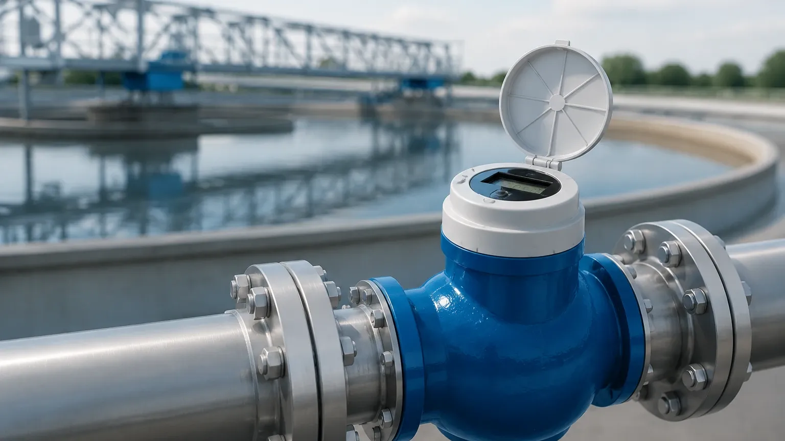
In modern industrial water management, precision and reliability are paramount. Whether managing a municipal supply, industrial wastewater, or chemical processing tanks, the ability to monitor fluid levels and flow rates without physical contact has revolutionized operational efficiency. The use of a 1 ultrasonic water meter—referring here to a singular high-precision ultrasonic unit or a 1-inch (DN25) diameter configuration—represents a critical component in automated process control.
This guide explores the engineering principles, selection criteria, and installation requirements for Ultrasonic Level Meters and their application in water-related environments. By understanding the underlying physics and environmental limitations, engineers can ensure long-term accuracy and reduced maintenance costs.
Understanding Ultrasonic Measurement Principles
Ultrasonic technology operates on the "Time-of-Flight" (ToF) principle. Unlike mechanical meters that rely on moving parts, ultrasonic instruments use acoustic waves to determine the distance to a liquid surface or the velocity of a moving fluid.
The Time-of-Flight Mechanism
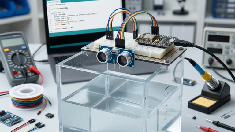
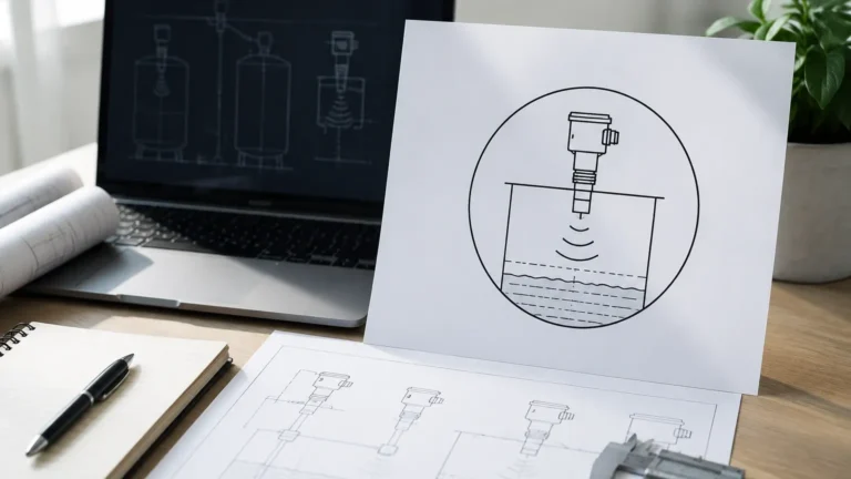
An ultrasonic transducer, typically constructed from piezoelectric crystals, emits a high-frequency sound pulse (usually between 20 kHz and 200 kHz). This pulse travels through the air, hits the surface of the water, and reflects back to the sensor. The instrument’s internal processor measures the time elapsed from emission to reception.
The distance is calculated using the formula:
D = (c × t) / 2
Where:
* D is the distance to the water surface.
* c is the speed of sound in the medium (air).
* t is the total travel time.
In level measurement applications, the device subtracts the measured distance (D) from the total tank height (H) to determine the actual water level (L). When configured as a 1 ultrasonic water meter for flow, the instrument may use either transit-time or Doppler effect principles to calculate volumetric flow rates based on the velocity of the water passing through a pipe of known diameter.
Applications of Ultrasonic Level Meters in Water Management
Ultrasonic instruments are preferred in water management due to their non-contact nature, which prevents corrosion and fouling. Common applications include:
1. Open Channel Flow: Used in conjunction with flumes or weirs to calculate flow rates in irrigation and wastewater treatment plants.
2. Storage Tank Monitoring: Providing real-time level data for chemical dosing tanks, raw water reservoirs, and treated water storage.
3. Pump Station Control: Automating pump start/stop cycles based on high and low-level setpoints.
4. Sewer and Drainage Monitoring: Detecting blockages or overflow conditions in municipal infrastructure.
Technical Specifications for a 1-Inch (DN25) Ultrasonic Configuration
When a project specifies a 1 ultrasonic water meter, it often refers to a DN25 pipe size for flow or a compact level sensor designed for small-scale tanks. Below are the typical technical parameters for such an instrument.
| Parameter | Typical Specification (DN25 / Small Tank) |
| :— | :— |
| Measurement Range | 0.1 m to 5.0 m (Level) / 0.1 to 10 m/s (Flow) |
| Accuracy | ±0.25% to ±0.5% of full scale |
| Output Signal | 4-20mA, RS485 (Modbus), or Pulse |
| Power Supply | 24V DC or Battery Powered |
| Operating Temperature | -20°C to +60°C |
| Enclosure Rating | IP66, IP67, or IP68 (Submersible) |
| Beam Angle | 6° to 12° |
Selection Criteria: Choosing the Right Instrument
Selecting the appropriate instrument requires more than just matching the pipe size or tank height. Engineers must evaluate the specific environment to avoid measurement errors.
1. The Dead Zone (Blocking Distance)
Every ultrasonic sensor has a "dead zone" immediately below the transducer face where it cannot receive an echo. For a standard level meter, this might range from 0.1 m to 0.5 m. If the water level rises into this zone, the meter will provide an erroneous reading or a "lost echo" error. Always ensure the highest possible water level remains below the dead zone.
2. Beam Angle and Obstructions
The ultrasonic pulse spreads as it travels, forming a cone. If this cone hits a tank wall, a ladder, or a support beam, the instrument may interpret the reflection as the water level. Choosing a sensor with a narrow beam angle (e.g., 6°) is essential for narrow tanks or pipes.
3. Material Compatibility
While the sensor does not touch the water, the housing and transducer face are exposed to the atmosphere within the tank. For clean water, standard ABS or PVC housings are sufficient. However, for wastewater or chemical-heavy environments, PVDF or PTFE-coated transducers are required to resist corrosive vapors.
Installation Best Practices and Environmental Considerations
Proper installation is the most significant factor in the performance of Ultrasonic Level Meters.
Mounting Position
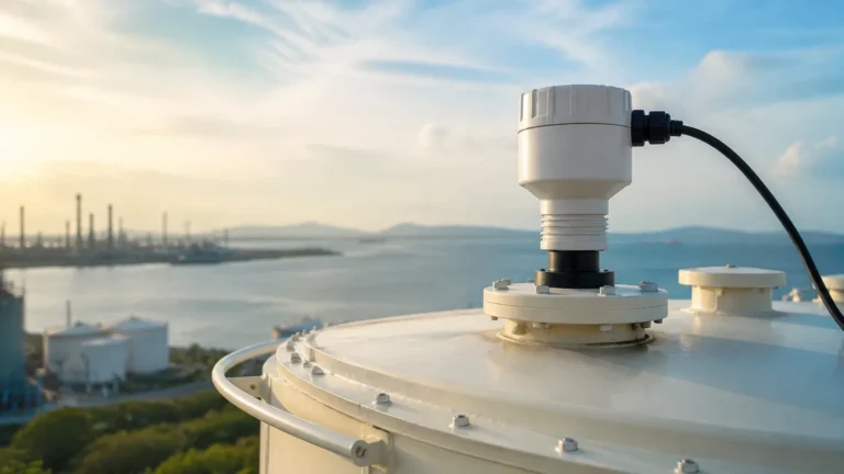
* Perpendicularity: The sensor must be mounted perfectly perpendicular to the water surface. A tilt of even a few degrees can cause the reflected signal to bounce away from the transducer, resulting in signal loss.
* Avoid the Center: In cylindrical tanks, do not mount the sensor in the exact center, as this can create parabolic echoes that amplify noise.
* Inlet Proximity: Keep the sensor away from water inlets to avoid interference from turbulent water or splashing.
Environmental Compensation
The speed of sound (c) changes with air temperature. A 1°C change in temperature can result in a 0.17% error in distance measurement. Professional-grade ultrasonic meters include an integrated temperature sensor to automatically compensate for these variations. However, if the sensor is in direct sunlight, the internal temperature may rise higher than the air temperature, leading to inaccuracies. In such cases, a sunshade is mandatory.
Limitations and Troubleshooting
While highly versatile, ultrasonic technology is not suitable for every application. Understanding these limitations prevents project failure.
* Foam: Heavy foam on the surface of the water absorbs the ultrasonic pulse rather than reflecting it. If foam is present, a hydrostatic pressure transmitter or a radar level meter is a better choice.
* Vapor and Steam: High concentrations of steam or chemical vapors can change the density of the air, significantly altering the speed of sound and causing large errors.
* Vacuum: Ultrasonic waves require a medium (air or gas) to travel. They cannot function in a vacuum.
* Turbulence: Extreme surface turbulence can scatter the signal. This can often be mitigated by using a stilling well or by increasing the damping/averaging settings in the instrument software.
Comparative Analysis: Ultrasonic vs. Other Technologies
To determine if a 1 ultrasonic water meter is the correct choice for your facility, compare it against common alternatives.
| Feature | Ultrasonic | Radar (Microwave) | Hydrostatic (Pressure) |
| :— | :— | :— | :— |
| Contact Type | Non-contact | Non-contact | Contact (Submerged) |
| Cost | Moderate | High | Low to Moderate |
| Effect of Foam | High Interference | Moderate Interference | No Interference |
| Effect of Vapor | High Interference | No Interference | No Interference |
| Maintenance | Very Low | Very Low | Moderate (Fouling) |
| Accuracy | High | Very High | Moderate |
Frequently Asked Questions
Can a 1 ultrasonic water meter measure flow in a partially filled pipe?
Yes, if configured as an area-velocity meter. It uses an ultrasonic level sensor to determine the "area" (how full the pipe is) and an ultrasonic Doppler sensor to determine the "velocity." Combined, these provide the volumetric flow rate.
What is the maximum range for these devices?
Standard industrial ultrasonic level meters typically reach up to 15 or 20 meters. For distances beyond 30 meters, radar technology is generally preferred due to the attenuation of sound waves over long distances.
How do I handle signal loss due to turbulence?
Most modern instruments allow for the adjustment of "blanking" and "averaging." By increasing the response time or using a stilling well (a vertical pipe that stabilizes the water surface), you can achieve a steady reading even in turbulent conditions.
Is calibration required frequently?
Because there are no moving parts, ultrasonic meters do not suffer from mechanical wear. Periodic verification is recommended, but recalibration is usually only necessary if the physical installation or the medium (gas composition) changes significantly.
Conclusion
Whether you are implementing a 1 ultrasonic water meter for a localized bypass line or integrating a network of Ultrasonic Level Meters across a treatment plant, the technology offers a robust, low-maintenance solution for water measurement. By accounting for the dead zone, ensuring perpendicular mounting, and considering environmental factors like temperature and foam, engineers can achieve highly accurate and repeatable data. For applications involving extreme steam or chemical foam, consulting with a technical specialist to compare ultrasonic performance against radar or hydrostatic alternatives is recommended to ensure the longevity of the installation.