Ultrasonic Level Sensor P&id Symbol
In the complex landscape of industrial process control, the Piping and Instrumentation Diagram (P&ID) serves as the primary blueprint for engineering design, operation, and maintenance. Among the various instruments depicted, level measurement devices are critical for inventory management and safety. Understanding the ultrasonic level sensor p&id symbol and the underlying technology of Ultrasonic Level Meters is essential for engineers, system integrators, and plant operators to ensure accurate communication and system reliability.
The Principle of Ultrasonic Level Measurement
Before diving into the symbolic representation on engineering drawings, it is vital to understand how these instruments function. Ultrasonic level measurement is a non-contact technology that utilizes sound waves to determine the distance between the sensor and the surface of a liquid or solid material.
How it Works
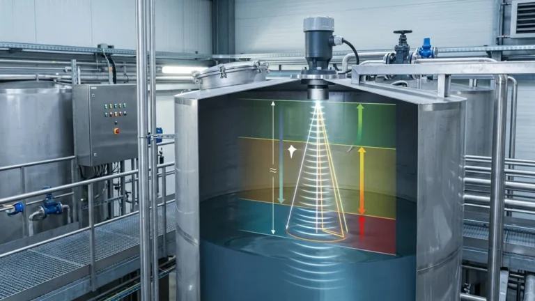
The sensor, typically mounted at the top of a tank or vessel, contains a piezoelectric crystal. This crystal converts electrical energy into mechanical energy in the form of high-frequency sound pulses (usually between 20 kHz and 200 kHz). These pulses travel through the air or gas space in the tank, hit the surface of the medium, and reflect back to the sensor as an echo.
The instrument calculates the distance ($D$) based on the Time-of-Flight (ToF) using the formula:
$$D = \frac{c \times t}{2}$$
Where:
* $c$ is the speed of sound in the medium (typically air).
* $t$ is the total time taken for the pulse to travel to the surface and back.
Since the height of the tank ($H$) is a known constant, the level of the material ($L$) is determined by subtracting the measured distance from the total height ($L = H – D$). Advanced transmitters then convert this level into a standardized output signal, such as 4-20mA, HART, or Modbus, for process control.
Deciphering the Ultrasonic Level Sensor P&ID Symbol
In accordance with international standards like ISA-5.1 (International Society of Automation), P&ID symbols are used to represent the function and physical location of instruments. The ultrasonic level sensor p&id symbol is not a single "picture" of the device but a combination of a geometric shape and alphanumeric codes.
1. The Instrument Bubble
The most common representation is a circle (often called a "bubble").
* A plain circle: Indicates the instrument is field-mounted (located at the tank).
* A circle with a horizontal line: Indicates the instrument is located in a primary control room or accessible to an operator.
* A circle with two horizontal lines: Indicates it is located in a secondary or local panel.
2. Letter Designations
The letters inside the bubble define the instrument's function. For an ultrasonic level system, you will typically see:
* LE (Level Element): Represents the actual ultrasonic transducer/sensor that emits the sound waves.
* LT (Level Transmitter): Represents the electronics that process the signal and transmit it to a controller. In many modern Ultrasonic Level Meters, the LE and LT are integrated into a single housing.
* LIC (Level Indicator Controller): Used if the ultrasonic meter is part of a control loop that manages a valve or pump.
* LSH / LSL (Level Switch High / Low): Used if the ultrasonic device is configured specifically for point-level alarms rather than continuous measurement.
3. Connecting Lines
The lines connecting the bubble to the process or other instruments also carry specific meanings:
* Solid Line: Represents the process connection (the physical mounting on the tank).
* Dashed Line: Represents an electrical signal (e.g., 4-20mA).
* Line with Circles or Slanted Marks: Often represents digital communication protocols like fieldbus or HART.
Technical Selection Criteria for Ultrasonic Meters
When specifying an ultrasonic level sensor based on a P&ID requirement, engineers must evaluate several technical parameters to ensure the device matches the application environment. Welk provides a range of industrial-grade solutions designed for diverse conditions.
| Feature | Consideration | Impact on Performance |
| :— | :— | :— |
| Measurement Range | Typically 0.1m to 30m. | Longer ranges require lower frequency sensors to overcome air attenuation. |
| Beam Angle | Usually 5° to 12°. | A narrower beam is better for narrow tanks or tanks with internal obstructions. |
| Frequency | 20 kHz to 80 kHz. | Higher frequencies offer better resolution but shorter range. |
| Process Temperature | Standard: -40°C to 80°C. | The speed of sound changes with temperature; internal compensation is required. |
| Operating Pressure | Usually near atmospheric. | High pressure increases the density of the gas, affecting sound propagation. |
Installation Best Practices
Correct installation is the difference between a reliable signal and constant "lost echo" errors. When translating a P&ID into a physical installation, consider the following:
The Blocking Distance (Dead Zone)
Every ultrasonic sensor has a "dead zone" directly beneath the transducer face where it cannot measure. This is the time required for the crystal to stop vibrating after emitting a pulse before it can listen for the echo. Ensure the maximum liquid level never enters this zone, or the reading will become erratic.
Positioning and Orientation
* Perpendicularity: The sensor face must be perfectly parallel to the liquid surface. Even a few degrees of tilt can cause the echo to reflect away from the sensor.
* Wall Interference: Do not mount the sensor too close to the tank wall. A general rule is to maintain a distance of at least 1/10th of the tank height from the wall to avoid false echoes from weld seams or scale.
* Obstructions: Ensure the "beam cone" is clear of ladders, pipes, or agitators. If obstructions are unavoidable, many Welk Ultrasonic Level Meters feature "false echo suppression" software to map out and ignore these static reflections.
Limitations and Environmental Factors
While ultrasonic technology is versatile, it is not a universal solution. Engineers should be aware of the following limitations:
1. Vacuum Conditions: Sound waves require a medium (gas/air) to travel. Ultrasonic sensors cannot function in a vacuum.
2. Heavy Foam: Thick, dense foam absorbs the ultrasonic pulse rather than reflecting it, leading to signal loss. In these cases, a radar or hydrostatic transmitter may be preferred.
3. Dust and Vapor: While light dust is manageable, extremely heavy dust or steam can attenuate the signal. High-power, low-frequency sensors are better suited for these environments.
4. Surface Turbulence: Rapidly churning liquid can scatter the sound waves. Using a stilling well or adjusting the damping software in the transmitter can help stabilize the reading.
Comparison: Ultrasonic vs. Other Technologies
In B2B procurement, choosing the right technology involves balancing cost and performance. The following table compares ultrasonic sensors with common alternatives found on P&IDs.
| Technology | Best For | Main Advantage | Main Limitation |
| :— | :— | :— | :— |
| Ultrasonic | Water, wastewater, chemical storage. | Non-contact, low maintenance, cost-effective. | Sensitive to foam and temperature gradients. |
| Radar (GWR/Non-contact) | High temp/pressure, hydrocarbons. | Unaffected by gas composition or vacuum. | Higher initial investment. |
| Hydrostatic | Deep wells, vented tanks. | Simple installation, unaffected by surface foam. | Contact-based; density changes affect accuracy. |
| Magnetic Gauges | High-pressure boilers, toxic fluids. | Visual indication + electronic output. | Requires bypass chamber; moving parts. |
Frequently Asked Questions (FAQ)
Q: Does the ultrasonic level sensor p&id symbol change if the sensor is wireless?
A: Yes. While the functional letters (LT) remain the same, the connecting line changes. Instead of a dashed line (electrical), a series of sine wave symbols or a specific wireless link symbol is used to indicate radio transmission.
Q: Can I use an ultrasonic sensor for solids?
A: Yes, but with caution. Solids like grain or plastic pellets have an "angle of repose" which can deflect the signal. You should choose a sensor with a higher power output and potentially a swivelling mounting flange to aim the sensor at the most representative point.
Q: How does temperature affect the P&ID specification?
A: The P&ID itself may not change, but the instrument data sheet must specify an integrated temperature sensor. Since the speed of sound in air changes by approximately 0.17% per degree Celsius, accurate level measurement is impossible without real-time temperature compensation.
Q: What is the standard output for these meters?
A: Most industrial Ultrasonic Level Meters provide a 4-20mA signal. In modern automated plants, this is often overlaid with a HART signal to allow for remote diagnostics and configuration.
Conclusion
The ultrasonic level sensor p&id symbol is a vital shorthand that conveys the functional intent of a level measurement loop. By combining a clear understanding of these symbols with a deep knowledge of ultrasonic principles and installation requirements, engineers can design more robust and maintainable systems. Whether you are managing water treatment facilities or chemical storage tanks, selecting high-quality instruments from a reliable manufacturer like Welk ensures that your physical installation lives up to the precision promised on the P&ID.