Ultrasonic Level Sensor Relay Output
Ultrasonic Level Sensor Relay Output: A Technical Guide for Process Automation
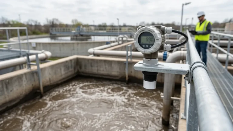
In modern industrial automation, the ability to monitor and control fluid levels without physical contact is a cornerstone of operational efficiency. While continuous monitoring via 4-20mA or RS485 signals provides a data stream for oversight, the integration of an ultrasonic level sensor relay output allows for direct, hardware-level control and safety interlocking. This functionality is essential for preventing tank overflows, managing pump cycles, and triggering localized alarms in water treatment, chemical processing, and general manufacturing environments.
As a professional manufacturer, Welk specializes in providing high-precision Ultrasonic Level Meters designed to withstand the rigors of industrial applications. Understanding the mechanics of how these sensors utilize relay outputs is critical for engineers and technicians tasked with designing reliable level-control systems.
Measurement Principles of Ultrasonic Level Meters
Before diving into the specifics of relay configurations, it is necessary to understand the underlying measurement principle. Ultrasonic level meters operate on the "Time-of-Flight" (ToF) principle.
The Time-of-Flight Mechanism
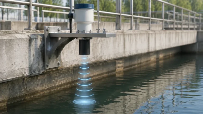
The sensor's transducer emits a high-frequency ultrasonic pulse (typically between 20 kHz and 200 kHz). This pulse travels through the air, reflects off the surface of the liquid or solid material, and returns to the transducer. The device measures the time elapsed between the emission and the reception of the echo.
Since the speed of sound in air is approximately 340 meters per second (at 20°C), the distance ($D$) from the sensor to the material surface can be calculated using the formula:
$$D = \frac{v \times t}{2}$$
Where:
* $v$ is the speed of sound in the medium (m/s).
* $t$ is the total time elapsed (s).
By subtracting this distance from the total tank height (the calibration distance), the meter determines the actual level of the medium. Most high-quality ultrasonic level meters from Welk include integrated temperature compensation, as the speed of sound varies significantly with air temperature changes.
Understanding the Ultrasonic Level Sensor Relay Output
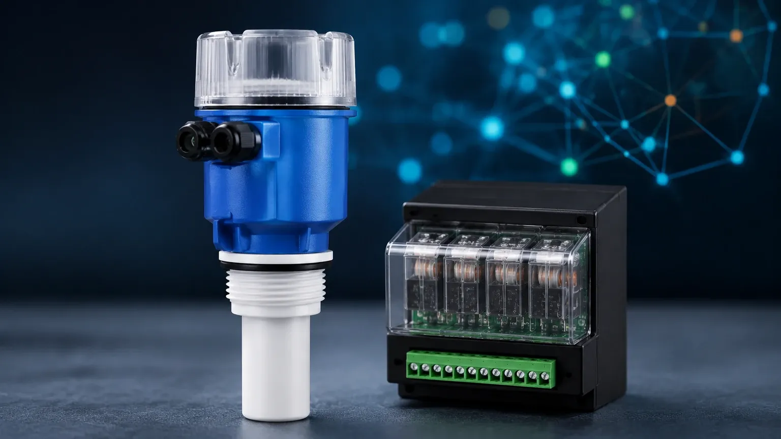
An ultrasonic level sensor relay output is a discrete switching signal provided by the instrument. Unlike the continuous analog output (which represents the exact level at any given time), the relay is a binary state: it is either "on" (closed) or "off" (open).
Types of Relay Configurations
Industrial sensors typically utilize one of two primary relay types:
1. SPDT (Single Pole Double Throw): This is the most common configuration. It consists of a common terminal (COM), a normally open (NO) terminal, and a normally closed (NC) terminal. When the level reaches a setpoint, the switch flips from NC to NO.
2. DPDT (Double Pole Double Throw): This provides two independent sets of SPDT switches controlled by the same level setpoint, allowing for the simultaneous control of two different circuits (e.g., a pump and a remote alarm light).
Fail-Safe Logic
Relay outputs can be configured for "Fail-Safe High" or "Fail-Safe Low." In a fail-safe configuration, the relay is energized during normal operation and de-energizes during an alarm state or power failure. This ensures that if the sensor loses power, the system defaults to a safe state (such as stopping a pump to prevent overflow).
Key Evaluation Criteria for Selection
When selecting an ultrasonic level meter with relay outputs, several technical specifications must be evaluated to ensure compatibility with the existing control infrastructure.
1. Switching Capacity
The relay's electrical rating determines what it can directly control. Most integrated relays are rated for low-power signals (e.g., 250 VAC / 5A or 30 VDC / 5A). If the application requires starting a high-horsepower pump, the sensor relay should trigger an external industrial contactor rather than switching the motor load directly.
2. Adjustable Hysteresis (Deadband)
Hysteresis is the difference between the "switch on" point and the "switch off" point. Without hysteresis, a turbulent liquid surface might cause the relay to chatter (rapidly cycle on and off) as the level fluctuates near the setpoint. A well-designed ultrasonic level sensor relay output allows the user to define a specific range (e.g., switch on at 2.0 meters, switch off at 1.8 meters) to stabilize the control loop.
3. Response Time and Damping
In applications with rapid level changes or surface agitation, adjustable damping filters out transient spikes in the level reading, preventing false relay triggers caused by splashes or momentary obstructions.
Practical Selection Table
| Feature | Specification Range | Practical Engineering Impact |
| :— | :— | :— |
| Number of Relays | 1 to 4 Relays | Allows for independent High, High-High, Low, and Low-Low alarm levels. |
| Contact Rating | 2A to 5A @ 250VAC | Determines if an intermediate relay/contactor is required for motor control. |
| Hysteresis | 0% to 100% of Range | Prevents relay chatter in turbulent tanks or pump-down applications. |
| Delay Time | 0 to 100 seconds | Filters out false echoes from agitators or surface turbulence. |
| Enclosure Rating | IP65 to IP68 | Crucial for outdoor or wash-down environments to protect electronics. |
Installation Considerations for Reliable Switching
The accuracy of the ultrasonic level sensor relay output is entirely dependent on the quality of the ultrasonic signal. Improper installation is the leading cause of relay failure or false alarms.
The Dead Zone (Blocking Distance)
Every ultrasonic sensor has a "dead zone" immediately below the transducer face (typically 0.2m to 0.5m depending on the model). If the liquid level enters this zone, the sensor cannot process the echo, leading to erratic readings or the relay locking in an error state. The sensor must be mounted high enough to ensure the maximum liquid level never enters this dead zone.
Mounting Orientation
The transducer face must be perfectly parallel to the liquid surface. A tilt of even a few degrees can cause the ultrasonic pulse to bounce off the surface and hit the tank wall instead of returning to the sensor, resulting in a "Lost Echo" error.
Internal Obstructions
Ultrasonic pulses spread out in a cone shape (usually 5° to 12°). If there are internal obstructions such as ladders, pipes, or agitator blades within this cone, the sensor may interpret them as the liquid level. Modern Welk sensors feature "False Echo Suppression," allowing the user to map out these fixed obstructions so they do not trigger the relay.
Limitations and Risks
While ultrasonic technology is versatile, certain environmental factors can interfere with the relay's reliability:
* Heavy Foam: Foam acts as an acoustic absorber. If the foam layer is thick and dense, the ultrasonic pulse may not return, causing the sensor to report a full or empty tank incorrectly.
* Vacuum or High Pressure: Ultrasonic waves require a medium (air/gas) to travel. They cannot function in a vacuum. High pressure can also alter the speed of sound and the density of the air, requiring specific calibration.
* Vapor and Dust: Heavy steam or dense dust can scatter the ultrasonic signal. In these specific cases, a radar level meter may be a more appropriate choice than an ultrasonic sensor.
* Turbulence: Rapidly moving surfaces can disperse the echo. Utilizing the damping features and setting appropriate hysteresis on the relay output is essential in these scenarios.
Frequently Asked Questions (FAQ)
Q: Can I use the relay output to control a pump directly?
A: It depends on the pump's power draw. Most sensor relays are rated for 5A. For industrial pumps, the sensor relay should drive the coil of a larger motor starter or contactor to prevent burning out the sensor's internal circuitry.
Q: How do I set up a pump-down (emptying) cycle using two relays?
A: You would set Relay 1 (High) to trigger the pump to start when the tank is full and Relay 2 (Low) to stop the pump when the tank is near empty. This logic is often built into the sensor's firmware, allowing for "Lead/Lag" pump control.
Q: What happens to the relay if the sensor loses the echo?
A: Most Ultrasonic Level Meters allow you to define a "Fail-Safe" state. You can program the relay to either hold its last known state, open, or close when an echo is lost for a predetermined period.
Q: Is the relay output affected by the chemical composition of the liquid?
A: No, because the measurement is non-contact. However, the chemical must not produce heavy vapors that significantly change the air density or corrode the transducer face. For corrosive environments, PVDF or PTFE-coated transducers are recommended.
Conclusion and Next Steps
The integration of an ultrasonic level sensor relay output provides a robust, cost-effective method for local process control. By understanding the measurement principles, respecting the installation requirements like the dead zone, and correctly configuring hysteresis and fail-safe modes, engineers can ensure long-term reliability in their level-monitoring systems.
When designing your next level-control project, it is vital to confirm the switching requirements and environmental conditions of your application. For technical support in selecting the right configuration for your specific industrial needs, you can explore the range of professional-grade Ultrasonic Level Meters and consult with application specialists to ensure your hardware choices align with your operational safety goals.