Ultrasonic Level Sensor with 4 20ma Output
Ultrasonic Level Sensor with 4-20mA Output: A Comprehensive Engineering Guide
In the landscape of industrial automation, precise level measurement is a cornerstone of process efficiency, safety, and inventory management. Among the various technologies available, the ultrasonic level sensor with 4-20mA output has emerged as a standard solution for non-contact measurement in liquid and solid applications. This guide examines the underlying physics, the technical integration of analog signals, and the practical considerations required for successful deployment in industrial environments.
Understanding the Measurement Principle: Time-of-Flight
Before selecting an Ultrasonic Level Meters for a specific application, it is essential to understand the Time-of-Flight (ToF) principle. An ultrasonic sensor operates by emitting high-frequency sound waves—typically between 20 kHz and 200 kHz—from a piezoelectric transducer.
1. Emission: The transducer converts electrical energy into mechanical vibrations, sending an ultrasonic pulse toward the target material.
2. Reflection: When the sound wave hits the surface of the medium (liquid or solid), a portion of the energy is reflected back toward the sensor as an echo.
3. Detection: The transducer, now acting as a receiver, detects the returning echo and converts it back into an electrical signal.
4. Calculation: The internal microprocessor measures the time interval between the emission and the reception. Since the speed of sound in air is known (approximately 343 m/s or 1,125 ft/s at 20°C), the distance (D) can be calculated using the formula:
*D = (Speed of Sound × Time) / 2*
The distance to the material level is then derived by subtracting the measured distance from the total tank height (the calibration distance).
The Role of the 4-20mA Analog Output
An ultrasonic level sensor with 4-20mA output utilizes a current loop signal, which is the most prevalent standard in the process control industry. This analog output represents the measured level as a current value ranging from 4 milliamperes (mA) to 20 milliamperes (mA).
Why 4-20mA is Preferred
* Noise Immunity: Unlike voltage signals (e.g., 0-10V), current signals are highly resistant to electromagnetic interference (EMI) and voltage drops over long cable runs. This makes them ideal for large industrial plants where sensors may be located hundreds of meters from the control room.
* Live Zero: The use of 4mA as the "zero" or "empty" point allows the system to distinguish between a low level and a system failure. If the current drops to 0mA, the control system (PLC/DCS) immediately recognizes a broken wire or power loss.
* Simplicity: It requires only two wires for both power and signal in many configurations, simplifying installation and reducing wiring costs.
In a typical configuration, 4mA might represent a 0% level (empty tank), while 20mA represents a 100% level (full tank). These parameters are usually programmable via the sensor’s interface to match the specific geometry of the vessel.
Key Evaluation and Selection Criteria
When specifying an ultrasonic level sensor with 4-20mA output, engineers must evaluate several technical parameters to ensure the device is compatible with the intended process.
1. Measurement Range and Dead Zone
Every ultrasonic sensor has a maximum range (the furthest distance it can measure) and a "dead zone" or "blocking distance" (the minimum distance required between the sensor face and the material). If the level enters the dead zone, the sensor cannot process the echo correctly, leading to false readings. Standard dead zones range from 0.2m (0.65 ft) to 0.8m (2.6 ft) depending on the power of the transducer.
2. Beam Angle
The ultrasonic pulse is not a laser beam; it spreads out in a conical shape. The beam angle (typically 5° to 12°) determines the footprint of the signal at a given distance. It is critical to ensure that no internal tank obstructions, such as ladders, pipes, or agitators, fall within this cone, as they will cause "false echoes."
3. Process Environment
* Temperature: The speed of sound varies with temperature. Reliable sensors must include an integrated temperature sensor to provide automatic compensation.
* Pressure: Ultrasonic sensors are generally designed for atmospheric or near-atmospheric pressure. High-pressure environments change the density of the air, significantly affecting sound wave propagation.
* Vapor and Dust: Heavy steam, chemical vapors, or dense dust can absorb or scatter the sound energy, reducing the effective range or accuracy.
Selection Table: Comparing Ultrasonic Sensor Configurations
| Feature | Integrated (Compact) Type | Remote (Split) Type | High-Power Long Range |
| :— | :— | :— | :— |
| Typical Range | 0.4m – 12m (1.3ft – 39ft) | 0.4m – 30m (1.3ft – 98ft) | Up to 40m+ (131ft+) |
| Output | 4-20mA (2-wire/4-wire) | 4-20mA + Relays | 4-20mA + RS485/HART |
| Installation | Single unit on tank top | Sensor on tank, display at eye level | Heavy-duty flange mount |
| Best For | Standard liquid tanks | Corrosive or high-heat areas | Large silos or deep wells |
| Complexity | Low | Moderate | High |
Installation Best Practices and Considerations
Proper installation is the single most important factor in the reliability of an ultrasonic level sensor with 4-20mA output. Following these guidelines prevents the most common field failures:
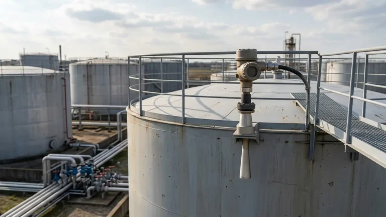
* Perpendicular Mounting: The transducer face must be perfectly parallel to the liquid surface. Even a slight tilt can cause the reflected signal to miss the receiver, resulting in a "Loss of Echo" (LOE) error.
* Avoid the Center: Do not mount the sensor in the exact center of a circular tank with a domed top. This can create a "parabolic effect," where multiple echoes converge and confuse the microprocessor.
* Stay Away from Inlets: Never install the sensor directly above the fill stream. The falling liquid will interfere with the ultrasonic pulse and create turbulent surfaces that scatter the signal.
* Substantial Mounting: Ensure the mounting bracket or flange is stable. Vibrations from pumps or agitators can introduce mechanical noise into the transducer, leading to unstable 4-20mA readings.

Limitations and Environmental Risks
While highly versatile, ultrasonic technology is not a universal solution. Engineers should be aware of the following limitations:
1. Vacuum Conditions: Sound waves require a medium (air or gas) to travel. Therefore, ultrasonic sensors cannot function in a vacuum.
2. Surface Foam: Light, airy foam is an excellent sound absorber. If a liquid surface is covered in thick foam, the sensor may fail to receive a return echo. In such cases, a hydrostatic transmitter or a magnetic level gauge may be more appropriate.
3. Extreme Turbulence: Rapidly churning liquids can scatter the signal. While software filtering (damping) can help stabilize the 4-20mA output, extreme cases may require a stilling well to provide a calm surface for measurement.
4. Temperature Gradients: If there is a significant temperature difference between the sensor and the liquid surface (e.g., in a heated tank), the sound speed compensation may become inaccurate.
Typical Industrial Applications
Welk’s ultrasonic level sensors are widely deployed across various sectors due to their non-contact nature, which eliminates the risk of corrosion or clogging from the process media.
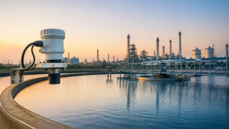
* Water and Wastewater Treatment: Monitoring levels in open channels, wet wells, chemical dosing tanks, and sludge pits. The 4-20mA signal is typically fed into a PLC to control pump cycles.
* Chemical Processing: Measuring acids, alkalis, and solvents in storage tanks where contact-based sensors would deteriorate.
* Food and Beverage: Monitoring ingredient silos or clean-water tanks where hygiene is paramount and non-contact measurement prevents contamination.
* Industrial Automation: General tank level monitoring in hydraulic power units, lubricant reservoirs, and cooling towers.
Frequently Asked Questions (FAQs)
Q: Can I use an ultrasonic sensor for solids like grain or sand?
A: Yes, but with caveats. Solids do not reflect sound as uniformly as liquids and often have an "angle of repose." This usually requires a sensor with higher power and a narrower beam angle to ensure a reliable return signal.
Q: How do I calibrate the 4-20mA range?
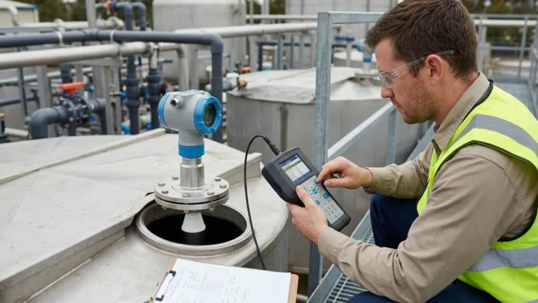
A: Most modern sensors feature a push-button interface or a digital menu. You define the "Near Point" (20mA/Full) and the "Far Point" (4mA/Empty) by entering the distance from the sensor face to those levels.
Q: What is the maximum cable length for the 4-20mA signal?
A: Depending on the wire gauge and the power supply voltage, 4-20mA signals can typically travel up to 1,000 meters (3,280 ft) without significant degradation.
Q: Does the sensor work in outdoor tanks?
A: Yes, provided the sensor has an appropriate Ingress Protection (IP) rating, such as IP65 or IP67. However, extreme weather like heavy snow or ice buildup on the transducer face will require maintenance.
Conclusion
The ultrasonic level sensor with 4-20mA output remains a primary choice for industrial level measurement due to its balance of accuracy, ease of integration, and low maintenance requirements. By understanding the acoustic principles and environmental factors that influence performance, engineering teams can implement reliable systems that provide consistent data for process control. For those requiring specific hardware recommendations or technical support for complex geometries, exploring professional-grade Ultrasonic Level Meters is the recommended next step in the project planning phase.
Download Ultrasonic Level Sensor with 4 20ma Output as a PDF