Ultrasonic Level Sensor P&id
Understanding Ultrasonic Level Sensor P&ID: A Guide to Specification and Implementation
In the realm of industrial process control, the Piping and Instrumentation Diagram (P&ID) serves as the primary blueprint for engineering design, operation, and maintenance. For engineers and technicians involved in fluid management, correctly identifying and documenting an ultrasonic level sensor p&id representation is critical for ensuring system integrity and operational clarity.
Ultrasonic level meters have become a staple in modern industry due to their non-contact nature, reliability, and cost-effectiveness. As a professional manufacturer, Welk provides advanced Ultrasonic Level Meters designed to integrate seamlessly into complex automated systems. This guide explores the measurement principles, P&ID standards, and practical selection criteria for these essential instruments.
Measurement Principles of Ultrasonic Level Meters
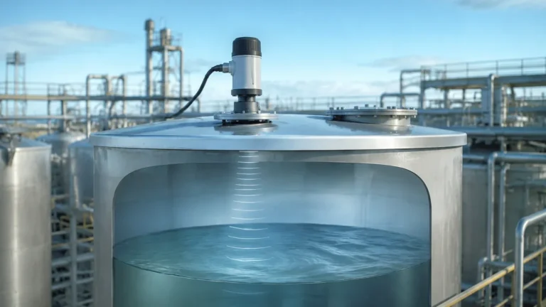
Before diving into the documentation aspects, it is vital to understand how these devices function. Ultrasonic level measurement is based on the "Time of Flight" (ToF) principle.
1. Emission: The sensor's transducer emits a high-frequency ultrasonic pulse (typically between 20 kHz and 200 kHz).
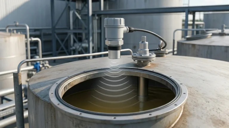
2. Propagation: This sound wave travels through the air space toward the material surface.
3. Reflection: Upon hitting the surface of the liquid or solid, the wave is reflected back toward the sensor.
4. Detection: The transducer receives the echo, and the internal electronics calculate the time elapsed between emission and reception.
The distance from the sensor to the material surface is calculated using the formula:
Distance = (Speed of Sound × Time) / 2
Since the speed of sound in air is approximately 343 m/s at 20°C but varies with temperature, high-quality Ultrasonic Level Meters usually include an integrated temperature sensor to compensate for these variations automatically.
Representing an Ultrasonic Level Sensor in P&ID
In a P&ID, instruments are represented by symbols and tag numbers following international standards, most commonly ISA-5.1. The ultrasonic level sensor p&id representation typically consists of a circle (bubble) containing a letter code and a unique loop number.
Common Tagging Conventions
* LE (Level Element): Represents the actual ultrasonic transducer that senses the level.
* LT (Level Transmitter): Represents the electronics that convert the sensor signal into a standardized output, such as 4-20mA or a digital bus signal.
* LIT (Level Indicator & Transmitter): Used when the device has a local display showing the level reading in addition to transmitting the signal.
* LSH/LSL (Level Switch High/Low): If the ultrasonic sensor is used specifically for point level detection or alarms.
Symbol Details
On a P&ID, a solid line connecting the bubble to the process vessel indicates the physical mounting location. A dashed line leading away from the bubble signifies an electrical signal (e.g., 4-20mA DC). If the sensor and transmitter are a single integrated unit (compact design), they are often represented by a single bubble labeled "LIT."
Selection Criteria for Industrial Applications
Choosing the right ultrasonic instrument requires an analysis of the process environment. Engineers should consult the following table during the specification phase:
| Feature | Specification Range | Practical Consideration |
| :— | :— | :— |
| Measurement Range | 0.1m to 30m (standard) | Ensure the maximum range exceeds the tank height by 10-20%. |
| Dead Zone | 0.1m to 0.6m | The distance from the sensor face where measurement is impossible. |
| Beam Angle | 5° to 12° | Narrower beams are better for avoiding internal tank obstructions. |
| Output Signal | 4-20mA, HART, RS485 | Compatibility with the PLC/DCS system is paramount. |
| Operating Temp | -40°C to +80°C | Accuracy fluctuates if the temperature is not properly compensated. |
| Protection Class | IP66, IP67, IP68 | Use IP68 for areas prone to flooding or heavy washdowns. |
Installation Guidelines for P&ID Accuracy
The physical installation of the sensor must match the intent shown on the ultrasonic level sensor p&id. Incorrect mounting is the most common cause of signal failure in ultrasonic systems.
1. The Dead Zone (Blocking Distance)
Every ultrasonic sensor has a "dead zone" immediately below the transducer face where it cannot receive echoes. If the liquid level rises into this zone, the sensor will report an error or a fixed value. In the P&ID design phase, the mounting nozzle height must be calculated to ensure the maximum liquid level never enters the dead zone.
2. Positioning and Obstructions
The ultrasonic pulse spreads in a conical shape. If the sensor is mounted too close to the tank wall or near internal structures like ladders, agitators, or heating coils, these objects will create "false echoes."
* Rule of Thumb: Mount the sensor at least 200mm away from the tank wall for every 1m of tank depth.
* Avoid the Center: In rounded tanks, mounting exactly in the center can cause multiple reflections that confuse the sensor.
3. Perpendicular Alignment
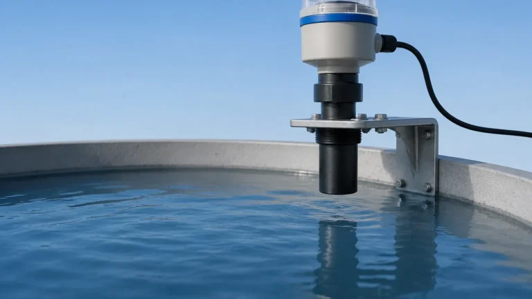
The transducer face must be perfectly parallel to the liquid surface. A tilt of even a few degrees can cause the reflected signal to miss the transducer, resulting in a "Loss of Echo" (LOE) error.
Applications and Industry Use Cases
Welk's Ultrasonic Level Meters are utilized across various sectors where non-contact measurement is preferred to avoid contamination or corrosion.
* Water and Wastewater: Monitoring levels in sumps, wet wells, and open channels. They are ideal for wastewater because they do not clog or foul like submersible pressure transducers.
* Chemical Processing: Measuring acids, bases, and solvents in storage tanks. Since the sensor does not touch the liquid, exotic materials are often unnecessary for the housing, though PVDF or PTFE faces may be used for vapor resistance.
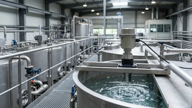
* Food and Beverage: Used in clean-in-place (CIP) environments where hygiene is critical. Non-contact sensors eliminate the risk of bacterial growth on submerged probes.

Limitations and Environmental Factors
While highly versatile, ultrasonic technology has specific limitations that must be accounted for in the process design:
* Heavy Foam: Thick foam can absorb the ultrasonic signal, preventing an echo from returning. In such cases, radar or hydrostatic sensors may be more appropriate.
* Vacuum or High Pressure: Sound requires a medium (air/gas) to travel. Ultrasonic sensors cannot function in a vacuum. High pressure also alters the speed of sound significantly, requiring specialized calibration.
* Vapor and Dust: Heavy steam or dense dust can scatter the sound waves, reducing the effective range of the instrument.
* Turbulence: Extreme surface agitation can scatter the echo. This can often be mitigated by using a stilling well or increasing the damping/averaging time in the sensor settings.
Maintenance and Troubleshooting
To ensure the ultrasonic level sensor p&id loop remains functional, regular maintenance checks should be performed:
1. Transducer Cleaning: In high-humidity environments, condensation or crystallization can form on the transducer face. Periodic wiping with a soft cloth ensures signal strength.
2. Signal Verification: Compare the LIT reading against a manual dip-tape measurement to verify calibration.
3. Check for Noise: Electrical noise from variable frequency drives (VFDs) can interfere with the low-voltage signal from the transducer. Ensure shielded cabling is used and grounded at one end.
Frequently Asked Questions (FAQ)
Q: Can an ultrasonic level sensor be used for solids?
A: Yes, but the range is typically reduced by 50% because solids (like grain or plastic pellets) absorb more sound and reflect it at irregular angles compared to liquids.
Q: What is the difference between an ultrasonic sensor and a radar sensor on a P&ID?
A: On a P&ID, they may look identical (both tagged as LT or LIT). The difference is noted in the instrument specification sheet. Radar is generally preferred for high-temperature, high-pressure, or foaming applications, while ultrasonic is more cost-effective for standard water and chemical tanks.
Q: How do I handle a tank with an agitator?
A: Most modern Ultrasonic Level Meters from Welk feature "False Echo Suppression" software. This allows the user to map out static obstructions (like agitator blades) so the sensor ignores them and only tracks the moving liquid surface.
Conclusion
Correctly specifying and documenting an ultrasonic level sensor p&id is a fundamental step in industrial engineering. By understanding the physical constraints of sound-based measurement—such as the dead zone, beam angle, and environmental interference—engineers can design more robust control systems.
For projects requiring precise, non-contact level monitoring, Welk offers a comprehensive range of solutions tailored to water treatment, chemical storage, and industrial automation. Integrating high-quality Ultrasonic Level Meters ensures that your process remains accurate, safe, and efficient.