Thermo Well
Thermo Well
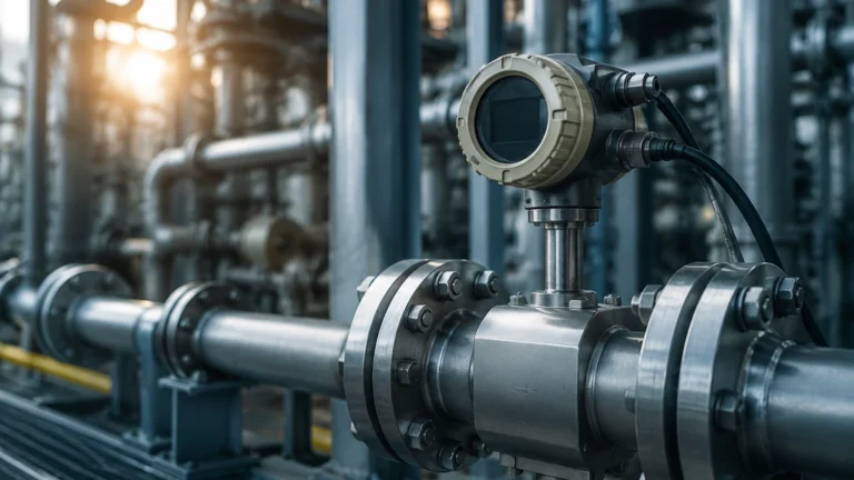
In industrial process control, the accuracy of measurement is only as reliable as the protection afforded to the sensing instruments. A thermo well is a critical component in this ecosystem, acting as a pressure-tight receptacle that protects temperature sensors—such as thermocouples, RTDs, and bimetal thermometers—from the harsh conditions of the process media. By isolating the sensor from high pressures, corrosive chemicals, and high-velocity flows, the thermo well ensures the longevity of the instrument while allowing for sensor maintenance or replacement without depressurizing the system.
For engineers and plant managers focused on comprehensive process monitoring, understanding the synergy between temperature and level measurement is vital. While companies like Welk specialize in advanced Main Page solutions for liquid and solid levels, the integration of temperature data via a robust thermo well is often necessary for density compensation and overall system safety.
Measurement Principles and Heat Transfer Dynamics
The fundamental principle of a thermo well is to facilitate heat transfer from the process fluid to the temperature sensor while maintaining a physical barrier. This process involves three primary stages of heat transfer: convection from the fluid to the outer surface of the well, conduction through the well wall, and finally, conduction and radiation from the internal well wall to the sensor.
Thermal Lag and Response Time
The presence of a thermo well inevitably introduces a delay in temperature measurement, known as thermal lag. The mass of the well must be heated or cooled before the internal sensor can register a change. To minimize this, engineers must consider the wall thickness and the fit between the sensor and the internal bore. A tight fit, often aided by heat-conductive paste, reduces the air gap and improves response times.
Conduction Error
Conduction error occurs when heat is transferred along the length of the thermo well to the ambient environment outside the pipe or vessel. If the insertion length is too short, the sensor may report a temperature closer to the ambient air than the actual process fluid. As a rule of professional practice, the sensitive portion of the sensor should be immersed deep enough into the flow to negate these stem-conduction effects.
Classification of Thermowell Designs
Thermowells are categorized based on their stem design and how they connect to the process. Each design serves a specific balance of mechanical strength and thermal sensitivity.
Stem Geometries
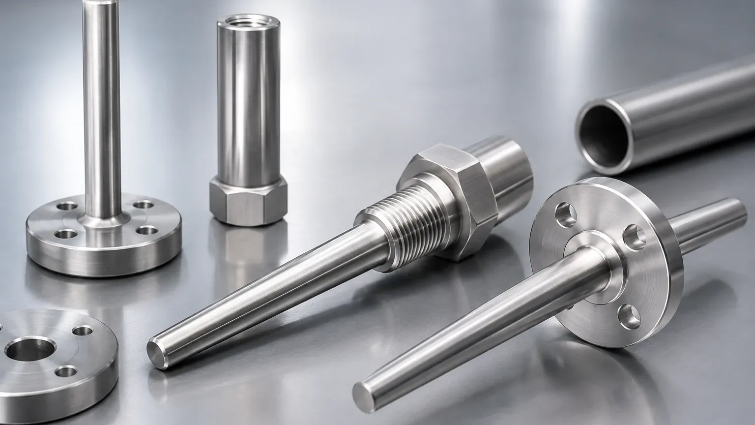
1. Straight Thermowells: These have a consistent diameter along the entire insertion length. They are simple to manufacture and provide decent strength but have a higher profile in the flow stream.
2. Stepped Thermowells: These feature a reduced diameter at the tip (usually 12.7 mm or 0.5 inches). The reduced mass at the sensing point significantly improves response time without sacrificing the mechanical strength of the mounting base.
3. Tapered Thermowells: These have a diameter that gradually decreases from the base to the tip. This design provides the highest structural integrity and a higher natural frequency, making them ideal for high-velocity applications where vibration is a concern.
Connection Types
* Threaded: Usually NPT or BSPT threads. These are common in low-pressure applications and smaller pipes where a simple screw-in installation is sufficient.
* Flanged: These utilize standard flange sizes (e.g., ANSI or DIN) to bolt onto a mating flange on the vessel. They are the standard for high-pressure, high-temperature, and highly corrosive environments.
* Socket Weld: The well is inserted into a socket and welded in place. This provides a permanent, leak-proof seal but makes replacement difficult.
* Weld-in: Directly welded into the process pipe, offering the highest pressure rating but no flexibility for removal.
Material Selection for Corrosive and High-Pressure Environments
Selecting the correct material for a thermo well is a matter of balancing chemical compatibility with mechanical durability. The material must withstand the process fluid's acidity or alkalinity while maintaining its shape under pressure.
| Material | Common Applications | Key Characteristics |
| :— | :— | :— |
| 316 Stainless Steel | Water treatment, food/beverage, general chemicals | Excellent corrosion resistance, cost-effective, standard for most industrial use. |
| Monel 400 | Sea water, hydrofluoric acid, sulfuric acid | High strength and excellent resistance to chloride-induced stress corrosion. |
| Hastelloy C-276 | Highly aggressive chemicals, wet chlorine gas | Exceptional resistance to pitting and oxidizing atmospheres. |
| Inconel 600 | High-temperature furnace applications | Maintains strength at temperatures exceeding 1000°C. |
| Tantalum (Sleeve) | Strong acids (Hydrochloric, Nitric) | Often used as a jacket over stainless steel for extreme chemical resistance. |
Engineering Selection Criteria and Comparison Table
When specifying a thermo well, engineers must evaluate the process conditions against the mechanical limits of the hardware. The following table provides a comparison of common selection factors.
| Feature | Threaded Well | Flanged Well | Tapered Stem | Stepped Stem |
| :— | :— | :— | :— | :— |
| Pressure Rating | Moderate | High to Very High | Very High | Moderate |
| Response Speed | Standard | Standard | Fast | Very Fast |
| Vibration Resistance | Low | Moderate | Excellent | Moderate |
| Ease of Maintenance | High | High | Moderate | Moderate |
| Typical Pipe Size | < 50 mm | > 50 mm | Any | Any |
Installation Best Practices for Accuracy and Longevity
Proper installation is as important as the design itself. A poorly installed thermo well can lead to inaccurate data or, worse, mechanical failure due to fatigue.
Insertion Length
For liquid applications, the insertion length (the distance from the tip to the bottom of the threads or flange) should ideally be equal to the pipe diameter or at least 8 to 10 times the well's tip diameter. In gas applications, where heat transfer is less efficient, the immersion should be even deeper—typically 10 to 15 times the tip diameter.
Orientation
* Perpendicular: The most common installation, where the well is at a 90-degree angle to the flow.
* Angled/Incline: Used in small-diameter pipes to increase the immersion length. The well is installed at a 45-degree angle pointing against the flow.
* Elbow Installation: The well is installed in a pipe elbow, with the tip pointing directly into the oncoming flow. This is often the preferred method for high-velocity steam lines.
Wake Frequency Calculations
One of the most overlooked risks is the Von Karman effect. As fluid flows past a thermo well, it creates vortices. If the frequency of these vortices matches the natural frequency of the well, resonance occurs, which can snap the well off at the base. Engineers should always perform a wake frequency calculation per ASME PTC 19.3 TW to ensure the well's dimensions are safe for the specific flow velocity.
Limitations and Potential Risks
While essential, a thermo well does have limitations that must be managed:
1. Measurement Lag: As discussed, the extra mass slows down the detection of rapid temperature swings. This can be problematic in safety-critical loops.
2. Erosion: In slurries or high-velocity particulate flows, the leading edge of the well can wear down over time, eventually exposing the sensor.
3. Pressure Drop: In smaller pipes, the presence of a thermo well acts as an obstruction, causing a localized pressure drop and potentially affecting flow measurements downstream.
4. Cleaning Challenges: In the food and pharmaceutical industries, the area where the well meets the pipe wall can become a "dead zone" for bacteria growth if not designed with sanitary (tri-clamp) fittings.
Integration with Level Measurement Systems
In the context of industrial automation, temperature data is rarely used in isolation. For instance, when using a hydrostatic level transmitter from the Welk product line, the accuracy of the level reading depends on knowing the density of the liquid. Since density changes with temperature, a thermo well-protected sensor provides the real-time data needed for the PLC to calculate the true level.
Similarly, for ultrasonic level sensors, the speed of sound through the vapor space is temperature-dependent. By installing a thermo well in the tank's headspace, the system can compensate for temperature fluctuations, ensuring that the level readings remain precise regardless of environmental changes. This holistic approach to instrumentation—combining reliable level meters with properly engineered temperature protection—is the hallmark of modern process efficiency.
Frequently Asked Questions (FAQs)
Q: How do I know if I need a tapered or a straight thermo well?
A: Tapered wells are generally preferred for high-velocity flows (above 5 m/s for liquids) because they offer a higher natural frequency and better resistance to vibration. Straight wells are suitable for lower velocity and lower pressure applications.
Q: Can I use a thermo well in a pipe smaller than 50 mm (2 inches)?
A: Yes, but it is recommended to use an elbow installation or an inclined installation. This ensures the tip is sufficiently immersed without blocking a significant portion of the pipe's cross-sectional area.
Q: What is the difference between "U" length and "L" length?
A: The "U" length is the insertion length—the distance from the mounting point to the tip of the well. The "L" length is the total length, including the lagging extension (the part that sticks out past the insulation of a pipe).
Q: Why is my temperature reading lower than expected?
A: This is often due to insufficient immersion length or poor thermal contact between the sensor and the well. Ensure the sensor is spring-loaded to maintain contact with the bottom of the well and check that the insertion depth follows the 10x diameter rule.
Conclusion
The thermo well is a deceptively simple component that carries significant responsibility in an industrial plant. By selecting the right geometry, material, and installation method, engineers can protect their sensitive instrumentation and ensure the accuracy of their process data. Whether you are managing a chemical reactor or a water treatment facility, the synergy between temperature protection and advanced level measurement remains a cornerstone of operational safety and efficiency. For those seeking to optimize their entire measurement loop, reviewing the comprehensive range of sensors on the Main Page is a recommended next step in building a resilient instrumentation strategy.