Ultrasonic Flow Meter Flare Gas
Ultrasonic Flow Meter Flare Gas
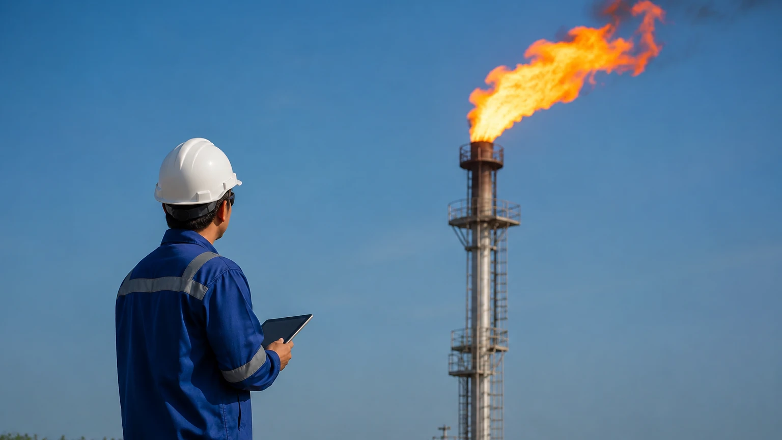
Flare gas measurement represents one of the most demanding challenges in industrial process monitoring. Unlike steady-state production lines, flare systems handle waste gases that vary wildly in composition, pressure, and flow velocity. To maintain environmental compliance and operational safety, the industry has largely standardized on the ultrasonic flow meter flare gas solution. This technology provides the necessary rangeability and reliability to monitor both the low-velocity pilot gas and the high-velocity emergency relief events common in refineries, chemical plants, and upstream oil and gas facilities.
Measurement Principles of Transit-Time Ultrasonic Technology
Before selecting a specific instrument, it is essential to understand the physics governing ultrasonic flow measurement in gas applications. Most flare gas meters utilize the "transit-time" or "time-of-flight" principle.
The Transit-Time Method
In this configuration, pairs of ultrasonic transducers are installed on opposite sides of the flare pipe, typically at an angle (often 45 degrees). One transducer acts as a transmitter, sending an ultrasonic pulse to the second transducer, which acts as a receiver. The system then reverses the roles, sending a pulse in the opposite direction.
When the gas is stationary, the time taken for the pulse to travel upstream and downstream is identical. However, when gas is flowing, the pulse traveling with the flow (downstream) moves faster than the pulse traveling against the flow (upstream). The difference in these transit times ($Δt$) is directly proportional to the velocity of the gas ($v$).
Speed of Sound and Molecular Weight
Beyond measuring velocity, ultrasonic meters calculate the Speed of Sound (SoS) within the gas. This is a critical secondary measurement in flare systems. Because the speed of sound varies based on the gas composition and temperature, the meter can provide a real-time estimation of the gas's average molecular weight. This allows operators to identify whether the flared gas is primarily light (like methane or hydrogen) or heavy (like butane or heavier hydrocarbons), which is vital for calculating mass flow and total emissions.
Why Ultrasonic Technology is Preferred for Flare Gas
Traditional flow measurement technologies, such as orifice plates or thermal mass meters, often struggle with the unique conditions of a flare header. Ultrasonic meters offer several distinct advantages:
1. Wide Turndown Ratio: Flare systems may experience extremely low flow during normal standby (pilot gas) and massive surges during a plant trip. Ultrasonic meters can handle a turndown ratio exceeding 1000:1, measuring velocities from as low as 0.01 m/s (0.03 ft/s) up to 100 m/s (328 ft/s) or higher.
2. No Pressure Drop: As non-intrusive or minimally intrusive devices, they do not obstruct the flow path. This is crucial for safety, as any restriction in a flare line could lead to dangerous overpressure upstream.
3. Low Maintenance: With no moving parts to wear out and transducers that can be designed to resist fouling, these meters offer high availability in harsh environments.
4. Bi-directional Measurement: They can detect and measure flow in both directions, which is useful for identifying backflow or internal leaks within complex header systems.
Technical Selection Criteria for Flare Gas Measurement
Selecting the right ultrasonic flow meter flare gas configuration requires a detailed analysis of the process conditions. Engineers must evaluate the following parameters to ensure accurate data and long-term performance.
Gas Composition and Attenuation
Flare gas is rarely pure. It often contains high concentrations of CO2, which is a strong absorber of ultrasonic energy. If the CO2 content is high, higher-power transducers or lower-frequency signals may be required to ensure the pulse reaches the receiver. Similarly, the presence of hydrogen, which has a very high speed of sound, requires high-speed electronics capable of processing rapid signal transitions.
Pipe Diameter and Path Configuration
Flare headers are often large, ranging from DN100 (4 inches) to over DN2000 (80 inches). For smaller pipes, a single-path meter may suffice. However, for larger diameters or where the flow profile is distorted by upstream bends, multi-path meters (2, 3, or 4 paths) are recommended. Multi-path systems average the velocity across different sections of the pipe, significantly increasing accuracy and reducing sensitivity to flow profile disturbances.
Pressure and Temperature Ranges
Standard flare systems operate near atmospheric pressure, but emergency events can cause rapid temperature spikes. Transducers must be rated for the full range of expected temperatures, often from -200°C (-328°F) for LNG applications to +250°C (+482°F) for refinery steam-out conditions.
Practical Selection Table
| Parameter | Requirement | Impact on Selection |
| :— | :— | :— |
| Velocity Range | 0.01 m/s to 100+ m/s | Requires high-dynamic-range electronics. |
| Accuracy | ±1% to ±5% of reading | Higher accuracy requires multi-path configurations. |
| Gas Composition | Variable (CH4, H2, CO2, H2S) | Influences transducer frequency and power. |
| Pipe Size | DN100 to DN2000 (4" to 80") | Determines the number of paths and mounting method. |
| Pressure | 0.8 bar to 10 bar (11 to 145 psi) | Affects signal coupling; low pressure is more difficult. |
| Straight Run | 20D Upstream / 10D Downstream | May require flow conditioners if space is limited. |
Installation and Engineering Best Practices
Even the most advanced ultrasonic flow meter flare gas system will fail to provide accurate data if installed incorrectly. Proper engineering at the installation phase is paramount.
Straight Pipe Requirements
To ensure a fully developed flow profile, the meter should ideally be placed in a straight section of pipe. The industry standard is typically 20 diameters (20D) of straight pipe upstream of the meter and 10 diameters (10D) downstream. If these distances cannot be met due to space constraints, computational fluid dynamics (CFD) modeling or the use of multi-path meters can help compensate for the resulting turbulence.
Transducer Mounting and Alignment
Transducers are typically installed using "hot tapping" or via dedicated spools. Hot tapping allows for installation without shutting down the flare system, which is a significant cost advantage. Precise alignment is critical; even a few degrees of misalignment can result in signal loss or significant measurement errors. Advanced mounting fixtures with laser alignment tools are often used during commissioning.
Insulation and Heat Tracing
In climates where ambient temperatures drop significantly, or if the gas contains heavy hydrocarbons that could condense, the pipe section containing the flow meter should be insulated. Liquid droplets (condensate) in the gas stream can scatter ultrasonic signals, leading to "signal attenuation" or a complete loss of measurement. In some cases, heat tracing is applied to the transducer ports to prevent ice or wax buildup.
Limitations and Risk Mitigation
While ultrasonic meters are highly versatile, they are not without limitations. Understanding these risks allows for better system design.
* Acoustic Noise: High-pressure drop valves (like control valves or pressure safety valves) located near the flow meter can generate ultrasonic noise. This noise can interfere with the meter's signal. Mitigation involves placing the meter as far as possible from such valves or using noise-attenuating silencers.
* Liquid Carryover: As mentioned, ultrasonic pulses do not travel well through two-phase flow (gas and liquid). The system should include a knock-out drum upstream of the measurement point to remove as much liquid as possible.
* Transducer Fouling: In "dirty" gas applications, soot or polymer buildup can coat the transducer faces. While many ultrasonic meters can "fire through" a certain amount of buildup, periodic cleaning or the use of retractable transducers (which can be serviced under pressure) is recommended.
Integrating Flow and Level Measurement in Industrial Automation
In a comprehensive industrial automation strategy, flow measurement is rarely an isolated data point. For instance, in flare knock-out drums, accurate level measurement is required to ensure that liquids do not reach the flare tip or the flow meter. Modern facilities utilize a combination of technologies to maintain safety.
As a professional manufacturer of industrial measurement instruments, Welk provides a range of solutions that complement flow systems. While the ultrasonic flow meter flare gas handles the gas phase, reliable Main Page solutions like radar level meters or ultrasonic level sensors are essential for monitoring the liquid levels in the associated separators and drums. Integrating these measurements into a centralized control system allows for automated pump-outs and emergency shutdowns, protecting both the environment and the facility's assets.
Frequently Asked Questions (FAQ)
Q: Can ultrasonic flow meters measure 100% hydrogen flare gas?
A: Yes, but it requires specialized high-speed signal processing. Hydrogen has a very high speed of sound (approx. 1300 m/s compared to 340 m/s for air), which shortens the transit time significantly. The electronics must be fast enough to resolve these very small time differences.
Q: How often do the transducers need to be calibrated?
A: Ultrasonic meters are inherently stable because they rely on time and distance. In many jurisdictions, a "dry calibration" or electronic verification is sufficient every 1 to 3 years, provided the internal diagnostics show the signal strength and signal-to-noise ratio remain within factory specifications.
Q: What happens to the measurement during a high-velocity emergency relief event?
A: Modern ultrasonic meters are designed to track velocities up to 100 m/s or more. During such events, the signal might become noisier due to turbulence, but the meter will generally continue to provide a reading, which is critical for post-event analysis and regulatory reporting.
Q: Is it possible to install an ultrasonic meter on a plastic or lined pipe?
A: For flare gas, the pipes are almost exclusively metallic (carbon or stainless steel). While ultrasonic signals can pass through plastic, flare applications usually require wetted transducers or specialized wave-guide mounts to handle the pressure and temperature requirements of the gas.
By following these selection and installation guidelines, process engineers can ensure that their ultrasonic flow meter flare gas system provides accurate, reliable data across the full spectrum of plant operating conditions. This not only ensures compliance with environmental mandates but also provides a vital layer of insight into plant efficiency and loss control.