
Rtd Temperature Transducer
Rtd Temperature Transducer
In the landscape of industrial process control, the accurate measurement of temperature is as critical as the measurement of pressure or flow. Among the various technologies available, the Resistance Temperature Detector (RTD) stands out for its exceptional stability and repeatability. However, an RTD element alone is often insufficient for modern automated systems. To bridge the gap between a raw physical resistance change and a programmable logic controller (PLC) or distributed control system (DCS), an RTD temperature transducer—frequently referred to as a temperature transmitter—is employed.
This guide explores the engineering principles, selection criteria, and industrial applications of RTD temperature transducers, particularly their indispensable role alongside level measurement instrumentation in complex process environments.
Fundamental Measurement Principles
The operation of an RTD temperature transducer is rooted in the predictable relationship between the electrical resistance of a metal and its temperature. This phenomenon is known as the Positive Temperature Coefficient (PTC), where electrical resistance increases as the temperature rises.
The RTD Element
Most industrial RTDs utilize platinum (Pt) due to its chemical inertness, wide temperature range, and highly linear resistance-to-temperature curve. The most common standard is the Pt100, which exhibits a resistance of exactly 100.00 Ω at 0°C (32°F). Other variations include Pt500 and Pt1000, which offer higher base resistance for specific high-sensitivity applications.
The relationship is mathematically defined by the Callendar-Van Dusen equation. For temperatures above 0°C, the formula is generally expressed as:
$$R_t = R_0 [1 + At + Bt^2]$$
Where:
* $R_t$ is the resistance at temperature $t$.
* $R_0$ is the resistance at 0°C.
* $A$ and $B$ are constants derived from the purity of the platinum.
The Transducer Function
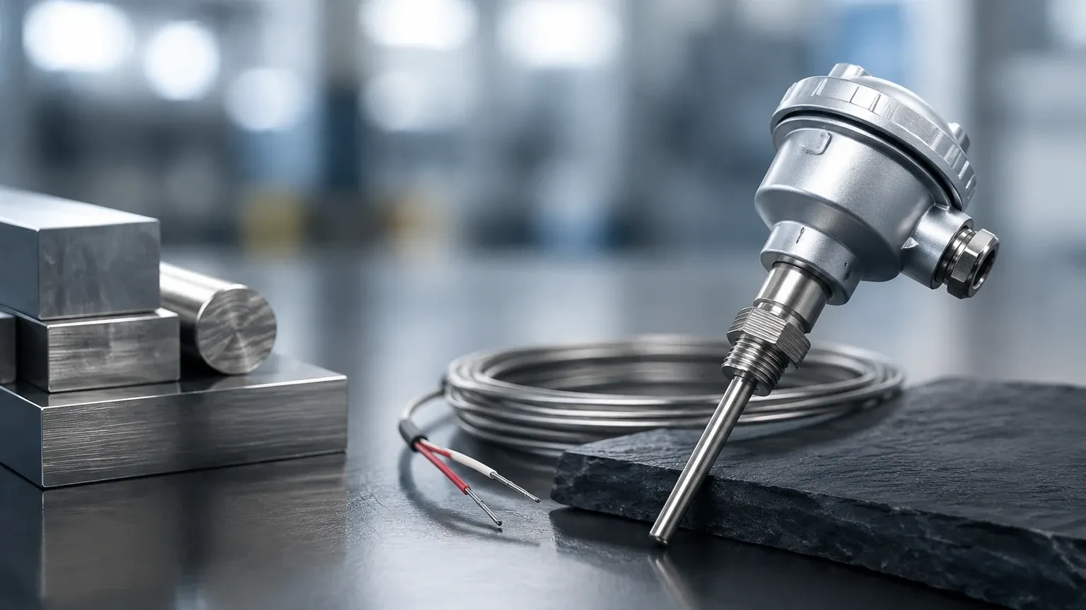
While the RTD element senses the temperature, the RTD temperature transducer is the electronic component that converts this low-level resistance signal into a standardized industrial signal. Without a transducer, the resistance signal would be susceptible to electromagnetic interference (EMI) and signal degradation over long cable runs. The transducer typically converts the resistance into a 4-20 mA current loop, a 0-10 V DC signal, or digital protocols such as HART, Foundation Fieldbus, or RS485 Modbus.
The Role of the Transducer in Signal Conditioning
An RTD temperature transducer performs several critical functions beyond simple signal conversion:
1. Linearization: Although platinum is relatively linear, it is not perfectly so. The transducer applies digital or analog linearization to ensure the output signal is directly proportional to the temperature.
2. Lead Wire Compensation: In industrial settings, the sensor may be located hundreds of meters from the control room. The resistance of the copper lead wires can add significant error. Transducers designed for 3-wire or 4-wire configurations can mathematically cancel out this lead resistance.
3. Isolation: High-quality transducers provide galvanic isolation between the input, output, and power supply. This protects sensitive control equipment from ground loops and high-voltage transients.
4. Signal Amplification: The resistance changes in an RTD are relatively small. The transducer amplifies these changes into a robust signal capable of traveling long distances without loss of integrity.
Synergy with Level Measurement Systems
In the context of industrial automation, temperature measurement is rarely an isolated requirement. For many users evaluating technologies on the Main Page, temperature data is a vital secondary variable for accurate level measurement.
Hydrostatic Level Compensation
Hydrostatic level transmitters measure the pressure exerted by a liquid column. However, the density of a liquid changes with its temperature. To calculate the exact level (height) from pressure, the system must know the current density. An RTD temperature transducer provides the real-time temperature data required for the PLC to perform density compensation, ensuring level accuracy remains constant even as process temperatures fluctuate.
Ultrasonic and Radar Level Accuracy
In ultrasonic level measurement, the speed of sound is directly affected by the temperature of the vapor space above the liquid. A temperature change of just 1°C can result in a significant measurement error if not compensated. Similarly, while radar level meters are less affected by temperature, extreme temperature gradients can influence the dielectric constant of certain vapors. Integrating an RTD temperature transducer allows for dynamic calibration of these sensors.
Technical Selection Criteria
Selecting the correct RTD temperature transducer requires an evaluation of both the process environment and the electrical requirements of the control system.
1. Wiring Configuration
* 2-Wire: Suitable only for short distances where high precision is not required. It cannot compensate for lead wire resistance.
* 3-Wire: The industrial standard. It uses a third wire to measure lead resistance and subtracts it from the total, providing a balance between cost and accuracy.
* 4-Wire: The most accurate configuration. It uses two wires to carry the excitation current and two independent wires to measure the voltage drop across the RTD, completely eliminating lead wire errors.
2. Output Protocol
* 4-20 mA (Analog): The most common choice for its noise immunity and simplicity.
* HART: Allows digital communication to be superimposed on the 4-20 mA signal, enabling remote diagnostics and configuration.
* Modbus/RS485: Preferred for multi-drop networks where many transducers are connected to a single bus.
3. Housing and Environment
Transducers may be head-mounted (installed directly inside the RTD connection head) or DIN-rail mounted (installed in a remote control cabinet). For hazardous areas, explosion-proof or intrinsically safe housings are mandatory. Protection ratings such as IP67 or NEMA 4X should be specified for wash-down or outdoor environments.
Practical Selection Table
| Feature | Pt100 (Class A) | Pt1000 | Thermocouple (Comparison) |
| :— | :— | :— | :— |
| Temperature Range | -200°C to +650°C | -200°C to +650°C | -270°C to +2300°C |
| Accuracy | Very High (±0.15°C) | High (±0.15°C) | Moderate (±1.0°C to 2.2°C) |
| Stability | Excellent | Excellent | Fair (Drifts over time) |
| Sensitivity | 0.385 Ω/°C | 3.85 Ω/°C | 10-60 µV/°C |
| Lead Wire Effect | Significant (requires 3/4 wire) | Low | Negligible |
| Best Use Case | Precision Industrial Process | Battery-powered/Low-power | High-temperature Furnaces |
Installation and Engineering Best Practices
To ensure the longevity and accuracy of an RTD temperature transducer, several installation factors must be considered:
Thermowell Usage
In pressurized or corrosive pipelines, the RTD element should never be exposed directly to the process media. A thermowell—a pressure-tight receptacle—is installed into the process, and the RTD is inserted into the thermowell. This allows for the removal of the sensor for calibration without shutting down the process. Heat transfer paste is often used inside the thermowell to reduce thermal lag.
Insertion Depth
A common error is insufficient insertion depth, leading to "stem conduction" error where heat escapes through the sensor housing. A general rule of thumb is an insertion depth of at least 10 times the diameter of the sensor probe (e.g., a 6mm probe should be inserted at least 60mm into the fluid stream).
Wiring and Grounding
* Use shielded twisted-pair cable for signal transmission to minimize EMI.
* Ground the shield at one end only (usually the controller end) to prevent ground loops.
* Avoid routing transducer cables parallel to high-voltage power lines.
Operational Limitations and Risks
While RTD temperature transducers are highly reliable, they are not without limitations:
* Self-Heating: To measure resistance, the transducer must pass a small current through the RTD. This current generates a tiny amount of heat. If the excitation current is too high, it can artificially raise the sensed temperature. High-quality transducers limit this current to less than 1 mA.
* Thermal Response Time: RTDs generally have a slower response time compared to thermocouples, especially when installed in heavy-duty thermowells. This must be accounted for in fast-acting control loops.
* Vibration: The fine platinum wire or thin-film element in an RTD can be fragile. In high-vibration environments, specialized vibration-resistant RTD constructions are required to prevent mechanical failure.
* Temperature Ceiling: RTDs are generally limited to temperatures below 650°C (1202°F). Beyond this point, the platinum can become contaminated or the internal insulation can break down, leading to significant drift.
Frequently Asked Questions (FAQs)
Q: Can I use a 2-wire RTD with a 3-wire transducer?
A: Yes, by placing a jumper wire between the compensation terminals on the transducer. However, you will lose the lead-wire compensation benefit, and the measurement will be less accurate.
Q: How often should an RTD temperature transducer be calibrated?
A: For most industrial applications, an annual calibration check is recommended. However, RTDs are known for their stability and often show less than 0.1°C of drift per year.
Q: What is the difference between an RTD and a Thermistor?
A: While both change resistance with temperature, RTDs are made of pure metals and are more linear and stable over a wider range. Thermistors are made of polymer or ceramic materials, are highly sensitive over a narrow range, but are generally less accurate for industrial process control.
Q: Why choose Pt1000 over Pt100?
A: Pt1000 sensors have a higher resistance, meaning the error introduced by lead wire resistance is a smaller percentage of the total measurement. This is particularly useful in 2-wire applications or battery-operated devices where lower current is preferred.
Conclusion
The RTD temperature transducer is a cornerstone of modern industrial instrumentation, providing the precision and stability required for high-stakes process monitoring. Whether used as a standalone sensor or as a critical compensation component for level measurement systems, understanding its principles and selection criteria is essential for any engineering project. For those seeking comprehensive solutions in industrial automation and measurement, exploring the technical resources and product options on the Main Page provides a foundation for building reliable, accurate, and cost-effective systems.


