Promag 400
Promag 400
In the field of industrial process control, the accurate measurement of fluid movement is as critical as the monitoring of storage volumes. While level measurement instruments—such as those found on the Main Page of specialized manufacturers—provide essential data on the status of tanks and silos, electromagnetic flowmeters like the Promag 400 serve as the primary tool for monitoring conductive liquids in closed pipe systems. Designed specifically for the water and wastewater industry, the Promag 400 transmitter, combined with various sensors, offers a robust solution for flow measurement, billing, and process optimization.
Understanding the technical nuances of the promag 400 requires an exploration of electromagnetic induction, sensor selection, and the integration of digital diagnostics. This guide provides a comprehensive technical overview for engineers and project managers evaluating flow measurement technologies alongside their level instrumentation requirements.
Measurement Principle: Faraday’s Law of Induction
The operation of the promag 400 is based on Faraday’s Law of Induction, a fundamental principle of electromagnetism discovered in 1831. According to this law, a conductor moving through a magnetic field induces an electrical voltage. In the context of an electromagnetic flowmeter, the liquid itself acts as the conductor.
The Physics of the Process
Inside the sensor of the promag 400, two electromagnetic coils are positioned to create a constant magnetic field perpendicular to the direction of flow. As the conductive liquid flows through the pipe, it passes through this magnetic field. The movement of the liquid induces a voltage ($U$) that is picked up by two electrodes located on opposite sides of the pipe wall.
The relationship is defined by the formula:
U = B · v · d
Where:
* U is the induced voltage.
* B is the magnetic field strength.
* v is the average flow velocity.
* d is the distance between the electrodes (the internal diameter of the pipe).
Since the magnetic field strength and the pipe diameter are constant, the induced voltage is directly proportional to the flow velocity. The promag 400 transmitter then processes this voltage signal, converts it into a flow rate (e.g., m³/h or l/s), and outputs the data via various communication protocols. It is important to note that this principle requires a minimum conductivity of the fluid, typically ≥ 5 µS/cm, to ensure a stable signal.
The Promag 400 Transmitter Features
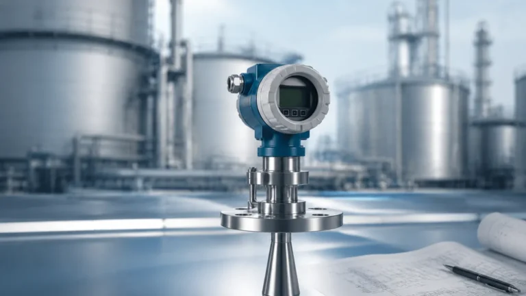
The "400" designation refers specifically to the transmitter—the electronic component that powers the coils and interprets the electrode signals. It is designed to be versatile, supporting both compact and remote installations.
Digital Integration and Web Server
One of the defining characteristics of the promag 400 is its integrated web server. This allows maintenance personnel to access device data, configuration settings, and diagnostic information using a standard web browser over a local network. This eliminates the need for specialized software or proprietary handheld terminals, significantly reducing commissioning time.
Heartbeat Technology
For critical infrastructure, the promag 400 often includes advanced diagnostic suites such as Heartbeat Technology. This system provides continuous self-monitoring and internal verification of the device's health without interrupting the process. It generates a verification report that can be used for regulatory compliance in water custody transfer or environmental monitoring.
Data Storage and Logging
The transmitter includes a built-in data logger and a removable SD card (HistoROM). This ensures that configuration data is backed up and can be easily transferred if the transmitter electronics need replacement. It also records event logs and process values for historical analysis.
Sensor Compatibility and Selection
The promag 400 transmitter is paired with different sensors depending on the application environment and pipe size. The most common sensors include the Promag W, Promag L, and Promag D.
Selection Table: Sensor Characteristics
| Feature | Promag W | Promag L | Promag D |
| :— | :— | :— | :— |
| Primary Application | Water & Wastewater | General Purpose / Weight-optimized | Space-restricted (Wafer) |
| Nominal Diameter (DN) | 25 to 3000 mm | 25 to 300 mm | 25 to 100 mm |
| Lining Materials | Hard rubber, Polyurethane, PTFE | Polyurethane, PTFE | Polyamide |
| Installation Type | Flanged | Flanged (Lap joint) | Wafer (Between flanges) |
| Corrosion Resistance | High (Certified for drinking water) | Moderate | Moderate |
Promag W (The Specialist for Water)
The Promag W is the most frequent partner for the 400 transmitter. It is available in very large diameters (up to DN 3000) and is often used in water intake, distribution, and wastewater treatment plants. It features a full-bore design, meaning there are no pressure losses and no moving parts to wear out.
Promag L (The Flexible Solution)
The Promag L is designed with lap-joint flanges, making it lighter and easier to install in systems where pipe alignment might be slightly off. It is often used in applications where weight reduction is necessary for plastic piping systems.
Installation Considerations
To achieve the specified accuracy (typically ±0.5% of the measured value), the promag 400 must be installed according to strict hydraulic guidelines. Improper installation is the leading cause of measurement drift and signal noise.
Inlet and Outlet Runs
Flow profiles must be fully developed and symmetrical for accurate measurement. Standard installations require:
* Inlet Run: 5 x DN (5 times the nominal diameter) of straight pipe before the sensor.
* Outlet Run: 2 x DN of straight pipe after the sensor.
If these distances cannot be met (e.g., due to space constraints), specialized "0 x DN" versions of the Promag W sensor are available, which use a multi-electrode design to compensate for turbulent flow profiles.
Orientation and Filling
The sensor must always be completely full of liquid. For this reason, vertical installation with an upward flow direction is preferred. If installed horizontally, the sensor should be placed at a low point in the piping system to prevent the accumulation of air bubbles, which would interfere with the electromagnetic field.
Grounding
Since the induced voltage is extremely small (millivolts), electrical noise from the piping system must be eliminated. The fluid, the sensor, and the transmitter must be at the same electrical potential. This is achieved using grounding rings or by connecting the sensor flanges to the metal piping.

Limitations and Common Risks
While the promag 400 is a highly reliable instrument, it is not suitable for every application. Engineers must be aware of the following limitations:
1. Conductivity Requirements: It cannot measure non-conductive fluids like hydrocarbons (oil, diesel) or demineralized water with conductivity below 5 µS/cm.
2. Vacuum Sensitivity: Certain liners, such as Polyurethane, can be damaged or pulled away from the pipe wall under vacuum conditions. For applications involving vacuum, PTFE liners with specialized support mesh are required.
3. Solids Content: While it can handle slurries, high concentrations of abrasive solids can wear down the liner over time. In such cases, hard rubber or specialized ceramic liners are preferred.
4. Ambient Temperature: The transmitter electronics have specific temperature limits (typically -20°C to +60°C). In extreme climates, sunshades or remote mounting of the transmitter may be necessary.
Synergies Between Flow and Level Measurement
In industrial automation, flow and level measurement are often two sides of the same coin. For instance, in a reservoir management system, a hydrostatic level transmitter (available through the Main Page of industrial suppliers) monitors the total volume of water available, while a promag 400 monitors the rate at which that water is being distributed to the network.
Mass Balance and Leak Detection
By comparing the flow rate entering a system (measured by the Promag 400) with the change in level in a storage tank (measured by an ultrasonic or radar level sensor), operators can perform a mass balance calculation. Discrepancies between these two values often indicate leaks or unauthorized withdrawals in the distribution network.
Pump Control
Integration of these two technologies allows for sophisticated pump control. Level sensors can trigger pump starts/stops based on tank capacity, while the flowmeter ensures the pump is operating within its optimal flow range, preventing cavitation and excessive wear.
Frequently Asked Questions (FAQ)
Q: Can the promag 400 measure the flow of gases?
A: No. Electromagnetic flowmeters require a conductive liquid to function. For gas measurement, technologies such as vortex, thermal mass, or ultrasonic flowmeters must be used.
Q: How often does the promag 400 need to be calibrated?
A: In many water applications, the device is stable for several years. However, regulatory requirements for billing or environmental discharge may mandate annual or biennial verification. Using Heartbeat Technology can extend the intervals between full wet calibrations by providing documented evidence of device health.
Q: What happens if the pipe is only partially full?
A: Standard electromagnetic flowmeters will provide inaccurate readings if the pipe is not full, as the calculation assumes a constant cross-sectional area (DN). Some versions include an "empty pipe detection" electrode to alert the system to this condition.
Q: Is the promag 400 compatible with older communication systems?
A: Yes, the transmitter supports a wide range of outputs, including 4-20mA HART, Modbus RS485, EtherNet/IP, and PROFINET, ensuring compatibility with both legacy PLC systems and modern IIoT frameworks.
Conclusion for Project Planning
When specifying instrumentation for a new facility or a retrofit, the promag 400 stands out as a reliable choice for conductive liquid flow measurement. Its combination of robust sensor options and a digitally advanced transmitter makes it suitable for the demanding environments of the water and wastewater sectors.
Before finalizing a purchase, project teams should confirm:
* The chemical compatibility of the liner material with the process fluid.
* The available straight pipe runs at the installation site.
* The required communication protocol for integration into the local SCADA system.
* The minimum and maximum expected flow velocities to ensure the sensor is sized correctly (ideally between 2 and 5 m/s for best accuracy).
For comprehensive process monitoring, ensure that your flow measurement strategy is complemented by high-quality level measurement instruments. Detailed specifications for level-related solutions can be reviewed on the Main Page of your preferred industrial instrumentation provider.