Vortex Flow Meter Dn100
Vortex Flow Meter Dn100
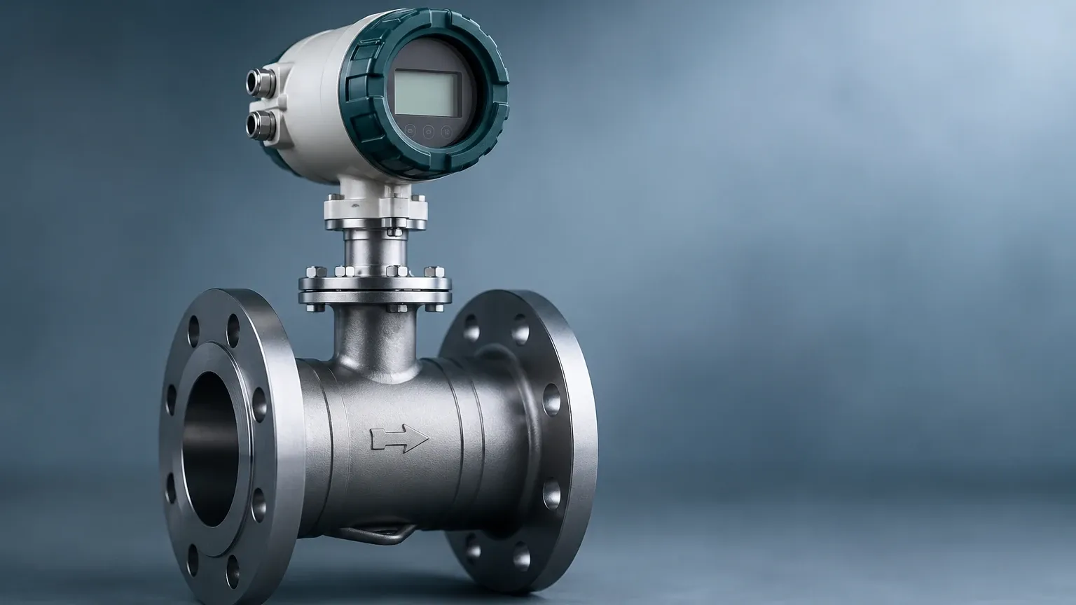
In the landscape of industrial process control, the measurement of fluid flow is as critical as the monitoring of tank levels. Among the various technologies available, the vortex flow meter stands out for its versatility, particularly in the DN100 (4-inch) size. This diameter is a common standard in medium-to-large scale industrial piping, serving as a primary conduit for steam, compressed air, and various gases. Understanding the technical nuances, installation requirements, and selection criteria for a vortex flow meter dn100 is essential for engineers seeking reliable data in challenging environments.
The Karman Vortex Street: Measurement Principle
Before selecting a specific instrument, it is vital to understand the physics governing vortex shedding. The operation of a vortex flow meter is based on the Karman Vortex Street principle, a phenomenon first described mathematically in the early 20th century.
When a fluid—whether liquid, gas, or steam—flows past a non-streamlined object (known as a bluff body or shedder bar) placed across the pipe diameter, it cannot follow the sharp contours of the body. As the fluid separates from the sides of the bluff body, it creates alternating low-pressure areas known as vortices. These vortices are shed in a staggered, periodic pattern downstream.
The frequency ($f$) at which these vortices are shed is directly proportional to the velocity ($v$) of the fluid and inversely proportional to the width ($d$) of the bluff body. This relationship is expressed through the Strouhal number ($St$):
$$f = St \times (v / d)$$
In a well-designed vortex flow meter dn100, the Strouhal number remains constant over a wide range of Reynolds numbers. Because the internal diameter of the DN100 pipe and the width of the shedder bar are fixed, the frequency of vortex shedding becomes a linear representation of the flow velocity. Sensors—typically piezoelectric crystals or ultrasonic detectors—embedded in or behind the shedder bar detect these pressure oscillations and convert them into electrical pulses, which the transmitter then scales into volumetric or mass flow rates.
Why DN100 is a Critical Specification
The designation "DN100" refers to a nominal diameter of 100 mm, which roughly equates to a 4-inch pipe. In industrial utility management, this size is frequently used for:
* Main Steam Headers: Distributing saturated or superheated steam from boilers to different plant sectors.
* Compressed Air Mains: Measuring the total output of large compressor rooms to identify leakage and optimize energy use.
* Water Distribution: Handling cooling water or treated process water in chemical and power plants.
* Natural Gas Feed Lines: Monitoring fuel consumption for large industrial kilns or furnaces.
At the DN100 scale, the vortex meter offers a significant advantage over orifice plates or Venturi meters because it has no moving parts to wear out and creates a lower permanent pressure loss, leading to long-term energy savings.
Technical Selection Criteria for DN100 Vortex Meters
Selecting the right vortex flow meter dn100 requires a deep dive into the process conditions. The following table provides a general reference for the performance expectations of a standard DN100 vortex meter across different media.
Table 1: Typical Flow Range for DN100 Vortex Flow Meter
| Medium | Minimum Flow (m³/h) | Maximum Flow (m³/h) | Typical Accuracy | Pressure Loss |
| :— | :— | :— | :— | :— |
| Liquid (Water) | 12 | 160 | ±0.75% to ±1.0% | Low |
| Gas (Air) | 150 | 1,800 | ±1.0% to ±1.5% | Moderate |
| Steam | 200 | 2,200 | ±1.5% to ±2.0% | Moderate |
*Note: Values are indicative and vary based on fluid density and operating pressure. For specific model configurations, engineers should consult the Main Page for detailed technical datasheets.*
Key Evaluation Factors
1. Reynolds Number (Re): Vortex shedding only becomes stable and linear above a certain Reynolds number, typically around 10,000 to 20,000. If the flow is too slow (laminar or transitional), the meter will not provide an accurate reading. For a DN100 pipe, this usually sets the "low-flow cutoff."
2. Fluid State: Vortex meters are excellent for "clean" fluids. While they can handle some suspended solids, high concentrations of abrasive particles can erode the shedder bar, changing its geometry and affecting the K-factor (pulses per unit volume).
3. Temperature and Pressure: For gas and steam applications, the density of the fluid changes with pressure and temperature. A "multivariable" vortex flow meter dn100 includes integrated temperature and pressure sensors to provide compensated mass flow readings automatically.
4. Material Compatibility: Standard bodies are often 304 or 316 stainless steel. However, for corrosive chemical applications, high-nickel alloys (like Hastelloy) may be required for the shedder bar and sensor housing.
Installation Guidelines for DN100 Piping
The accuracy of a vortex flow meter is highly dependent on the velocity profile of the fluid as it enters the meter. Disturbed flow leads to irregular vortex shedding and measurement errors.
Straight Pipe Requirements
To ensure a fully developed turbulent flow profile, the following minimum straight-run distances are recommended for a DN100 installation:
* Upstream of the Meter:
* After a single 90° elbow: 20D (2,000 mm)
* After two 90° elbows in different planes: 40D (4,000 mm)
* After a reducer: 15D (1,500 mm)
* After a partially open valve: 50D (5,000 mm)
* Downstream of the Meter:
* General requirement: 5D (500 mm)
Orientation and Support
* Horizontal Lines: The meter can be installed with the electronics housing on top, side, or bottom. For steam applications, side-mounting is often preferred to prevent condensate from pooling around the sensor or overheating the electronics.
* Vertical Lines: Flow must always be upward. This ensures the pipe remains full of liquid (in liquid applications) and prevents gas bubbles from interfering with the shedding frequency.
* Vibration Mitigation: Vortex sensors are sensitive to pipe vibration, which the electronics might mistake for flow signal. In DN100 lines, which carry significant mass, robust pipe supports should be installed on both sides of the meter to dampen mechanical noise.
Limitations and Common Risks
While the vortex flow meter dn100 is a robust tool, it is not a universal solution. Engineers must be aware of its limitations:
1. Low-Flow Sensitivity: Because the shedding frequency is proportional to velocity, there is a minimum velocity (typically 0.3 m/s for liquids and 3 m/s for gases) below which the signal disappears. If a process requires measurement at very low turn-down ratios, a vortex meter may not be suitable unless the pipe is reduced (e.g., using a DN80 meter in a DN100 line).
2. Cavitation: In liquid applications, if the pressure drops too low at the shedder bar, the liquid may flash into vapor (cavitation). This not only destroys the measurement signal but can also physically pit and damage the internal components of the meter.
3. Viscosity Limits: Highly viscous fluids (above 10-20 centipoise) dampen vortex formation. Vortex meters are generally unsuitable for heavy oils or thick slurries.
4. Signal Noise: In applications with high-frequency mechanical vibration or pulsating flow (such as downstream of a reciprocating compressor), the meter may provide erratic readings. Using digital signal processing (DSP) in the transmitter can help filter this noise, but it cannot eliminate it entirely.
Frequently Asked Questions (FAQ)
Q: Can a DN100 vortex meter measure wet steam?
A: It can measure the flow, but the accuracy will decrease. Vortex meters assume a single-phase fluid. High moisture content in steam (low steam quality) adds mass that the meter cannot accurately account for without additional instrumentation. For high-precision steam billing, a steam separator should be installed upstream.
Q: How often does a vortex flow meter dn100 need calibration?
A: Because there are no moving parts to wear, the K-factor of a vortex meter is extremely stable. In clean service, recalibration is often only required every 2 to 5 years, depending on local regulations or quality management systems. Many users perform a "zero-check" and electronics verification annually instead of a full wet calibration.
Q: What is the difference between Wafer and Flanged connections for DN100?
A: A wafer-style meter is sandwiched between existing pipe flanges using long bolts. It is lighter and less expensive. A flanged meter has its own built-in flanges that bolt directly to the pipe. Flanged versions are generally preferred for DN100 and larger sizes because they are easier to align and provide a more secure seal in high-pressure or high-vibration environments.
Q: Does the meter require a specific power supply?
A: Most modern vortex transmitters are 2-wire, 4-20mA loop-powered devices (24V DC). However, multivariable versions with integrated pressure/temperature compensation or those with backlit displays and HART/Modbus communication may require higher current or separate power leads.
Conclusion: Selecting the Right Solution
The vortex flow meter dn100 remains a cornerstone of industrial flow measurement due to its reliability and low maintenance requirements. By adhering to strict installation guidelines—particularly regarding straight pipe runs and vibration control—operators can achieve precise measurement for years. When integrating these flow solutions with broader plant automation, including level measurement and pressure monitoring, it is essential to source equipment from manufacturers who understand the rigors of the industrial environment. For further technical specifications and to explore a range of measurement instruments, engineers are encouraged to visit the Main Page for comprehensive product support and application guidance.