Ultrasonic Meter
Ultrasonic Meter
In the landscape of industrial automation and process control, the ultrasonic meter has established itself as a cornerstone technology for non-contact level measurement. Primarily utilized for monitoring liquids and bulk solids in tanks, silos, and open channels, these instruments leverage acoustic wave propagation to determine the distance to a material surface. As industries move toward more integrated and maintenance-free sensing solutions, understanding the engineering principles, selection criteria, and installation nuances of the ultrasonic meter is essential for ensuring operational efficiency.
Measurement Principles of Ultrasonic Technology
The fundamental operation of an ultrasonic meter is based on the "Time-of-Flight" (TOF) principle. The instrument consists of a transducer that contains a piezoelectric crystal. When energized, this crystal vibrates at a specific frequency, emitting a burst of ultrasonic sound pulses toward the target medium.
The Time-of-Flight Calculation
Once the pulse is emitted, it travels through the air (or gas space), strikes the surface of the medium, and reflects back to the transducer. The transducer then acts as a receiver, converting the returning mechanical energy back into an electrical signal. The internal microprocessor calculates the distance ($D$) using the following formula:
$$D = \frac{c \cdot t}{2}$$
Where:
* $c$ is the speed of sound in the medium (typically air, approximately 343 m/s or 1,125 ft/s at 20°C).
* $t$ is the total time elapsed between emission and reception.
Since the meter measures the distance from the sensor face to the product surface, the actual level of the material is derived by subtracting this distance from the total height of the vessel (the calibration distance).
Temperature Compensation
A critical factor in ultrasonic measurement is the speed of sound, which is highly dependent on the temperature of the gas through which the pulse travels. For instance, in air, the speed of sound changes by approximately 0.17% per degree Celsius. To maintain accuracy, modern ultrasonic meters include an integrated temperature sensor to provide real-time compensation for these fluctuations. In applications with significant temperature gradients, external temperature probes may be required to provide a more representative average temperature of the vapor space.
Key Evaluation Criteria for Selection
Selecting the appropriate ultrasonic meter requires a detailed analysis of the process environment and the physical properties of the medium. Engineers must balance performance requirements with cost-effectiveness.
1. Measurement Range and Frequency
Ultrasonic meters operate at different frequencies, typically ranging from 20 kHz to 70 kHz. Lower frequencies have longer wavelengths and can travel further, making them suitable for long-range measurements (up to 30 meters / 98 feet) or for penetrating dust and steam. Higher frequencies offer better resolution and smaller "dead zones" but are limited to shorter ranges (typically 5 to 10 meters / 16 to 33 feet).
2. Medium Characteristics
* Liquids: Generally provide an excellent reflective surface. However, turbulent surfaces or the presence of foam can scatter or absorb the ultrasonic signal.
* Solids: Bulk solids like grains, powders, or ores often have an angle of repose. This means the surface is not perpendicular to the sensor, which can cause the signal to reflect away from the transducer. In such cases, a high-power ultrasonic meter or a swiveling mounting flange may be necessary.
3. Chemical Compatibility
The transducer face is the only part of the instrument exposed to the process. For corrosive environments, such as acid storage or wastewater treatment, transducers are often constructed from or coated with PVDF (Polyvinylidene Fluoride) or PTFE (Teflon) to prevent chemical degradation.
Selection Table: Ultrasonic Meter Series Comparison
| Feature | Standard Liquid Series | High-Power Solids Series | Chemical Resistant Series |
| :— | :— | :— | :— |
| Max Range | 10m (33 ft) | 30m (98 ft) | 15m (49 ft) |
| Frequency | 50-70 kHz | 20-30 kHz | 40-50 kHz |
| Beam Angle | 8° – 10° | 5° – 7° | 8° – 12° |
| Housing Material | ABS / Polycarbonate | Aluminum Alloy | PVDF / PTFE |
| Typical Application | Water tanks, Sumps | Grain silos, Cement | Chemical dosing, Acids |
For more detailed technical specifications and to explore specific model capabilities, you can Review product options and application support on our Main Page.
Installation Considerations and Best Practices
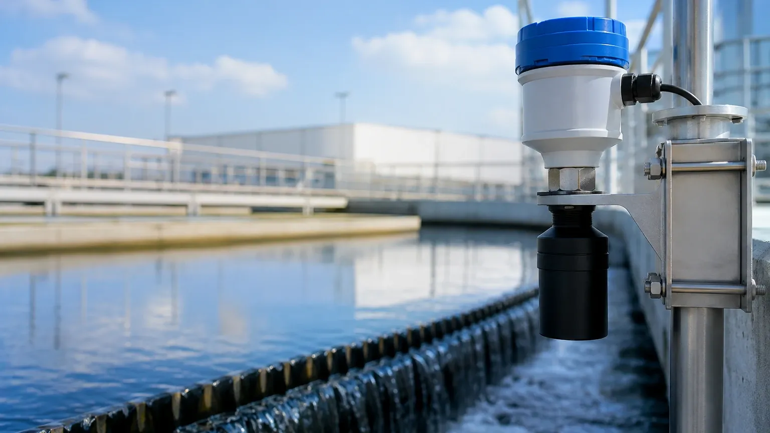
The reliability of an ultrasonic meter is heavily dependent on correct physical installation. Even the most advanced signal processing cannot compensate for a poorly positioned sensor.
The Blocking Distance (Dead Zone)
Every ultrasonic meter has a "blocking distance" or "dead zone" directly beneath the transducer face. This is the time required for the transducer to stop vibrating after emission and become ready to receive. If the material level enters this zone, the meter will provide an erroneous reading or a "lost echo" error. Users must ensure the sensor is mounted high enough so that the maximum possible level never reaches the blocking distance.
Avoiding Internal Obstructions
The ultrasonic pulse spreads out in a cone (the beam angle). Any internal structures within this cone—such as ladders, pipes, agitators, or weld seams—will create false echoes.
* Rule of Thumb: Mount the sensor at least 200mm (8 inches) away from the tank wall for every 1 meter (3.3 feet) of depth to avoid wall interference.
* Clearance: Ensure the center of the beam is unobstructed. If obstructions are unavoidable, many modern meters offer "False Echo Suppression" software to map out and ignore these static reflections.
Orientation
The transducer face must be installed parallel to the surface of the medium. In liquid applications, this usually means a vertical orientation. For solids, a specialized aiming kit may be used to align the sensor with the expected angle of the material pile to maximize signal return.
Limitations and Common Risks
While the ultrasonic meter is versatile, it is not a universal solution. Certain process conditions can severely attenuate the acoustic signal.
1. Vacuum Conditions: Sound requires a medium to travel. Ultrasonic meters cannot function in a vacuum.
2. Heavy Foam: Dense foam on a liquid surface acts as an acoustic absorber. If the foam is thick enough, the pulse will not reflect, leading to signal loss. In these scenarios, radar or hydrostatic transmitters are often preferred.
3. High Pressure and Vapor Layers: Significant changes in pressure (above 3 bar / 43 psi) alter the density of the air, affecting sound speed and signal strength. Similarly, heavy vapor layers (like concentrated solvent vapors) can change the composition of the gas space, leading to inaccurate distance calculations unless the meter is specifically calibrated for that gas.
4. Extreme Dust: While low-frequency meters can handle some dust, extremely heavy dust clouds (common during silo filling) can scatter the ultrasonic energy.
Frequently Asked Questions (FAQs)
Q: Can an ultrasonic meter be used for pressurized tanks?
A: Generally, ultrasonic technology is best suited for atmospheric or low-pressure vessels. High pressure changes the acoustic impedance of the gas, which can interfere with the transducer's ability to vibrate effectively. For high-pressure applications, radar level meters are usually the superior choice.
Q: How do I handle turbulence in the tank?
A: Turbulence can cause the level reading to jump. This is typically managed via software damping (averaging the readings over a set period) or by installing a stilling well—a vertical pipe that protects the liquid surface from agitation, providing a calm area for the ultrasonic pulse to measure.
Q: Does the color of the liquid affect the measurement?
A: No. Unlike optical sensors, ultrasonic meters use sound waves, so the color, transparency, or opacity of the liquid has no impact on the accuracy of the measurement.
Q: What maintenance is required for an ultrasonic meter?
A: Because they are non-contact, maintenance is minimal. Periodically check the transducer face for condensation or material buildup, especially in sticky or high-humidity applications. Most sensors can be wiped clean with a soft cloth and mild detergent.
Summary for Engineering Procurement
When specifying an ultrasonic meter for a project, the following data points should be confirmed with the manufacturer:
* Process Temperature and Pressure: To ensure the sensor housing and compensation algorithms are sufficient.
* Vessel Dimensions: To determine the required range and beam angle clearance.
* Medium Properties: Specifically the presence of foam, dust, or corrosive vapors.
* Output Requirements: Standard 4-20mA, Modbus RS485, or Hart protocols for integration into the local PLC/SCADA system.
By adhering to these engineering guidelines and understanding the physical constraints of acoustic measurement, project managers can implement ultrasonic solutions that provide years of reliable, maintenance-free service. For further assistance in selecting the right instrument for your specific industrial application, visit our Main Page to consult with our technical team.