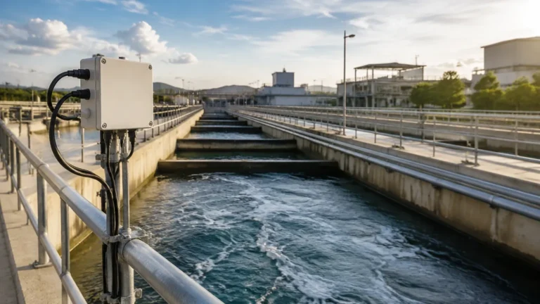
Differential Pressure
Differential Pressure
In the field of industrial process control, differential pressure (DP) remains one of the most versatile and widely adopted principles for measuring liquid level, flow, and density. While newer technologies like radar and ultrasonic sensors have gained significant market share, differential pressure transmitters continue to be a cornerstone for many engineers due to their reliability in high-pressure environments, their well-understood physics, and their cost-effectiveness in specific applications. For a comprehensive look at the full range of instrumentation available for these tasks, professionals often consult the Main Page of specialized manufacturers to compare DP systems with alternative electronic measurement methods.
Understanding the nuances of differential pressure is essential for selecting the right instrument, ensuring accurate installation, and maintaining system integrity over time. This guide explores the fundamental principles, application scenarios, and practical engineering considerations for DP-based level measurement.
Measurement Principles of Differential Pressure
The use of differential pressure for level measurement is based on the principle of hydrostatic head. In a liquid column, the pressure exerted at the base is directly proportional to the height of the liquid and its specific gravity (density).
The Hydrostatic Formula
The fundamental equation used in DP level measurement is:
P = ρ × g × h
Where:
* P is the hydrostatic pressure (Pascals, Pa).
* ρ (rho) is the density of the liquid (kg/m³).
* g is the acceleration due to gravity (approximately 9.81 m/s²).
* h is the height of the liquid column (meters, m).
A differential pressure transmitter measures the difference between two points. In a level application, the "High Pressure" (HP) side is typically connected to the bottom of the vessel, while the "Low Pressure" (LP) side is connected to the top of the vessel or vented to the atmosphere.
Open vs. Closed Vessels
The configuration of the DP system depends entirely on whether the tank is open to the atmosphere or pressurized.
1. Open Vessels: In an atmospheric tank, the LP side of the transmitter is vented to the air. The transmitter only measures the pressure exerted by the liquid column at the HP tap. Since the atmospheric pressure acts equally on the liquid surface and the LP port of the transmitter, it cancels out, leaving only the hydrostatic pressure of the liquid.
2. Closed (Pressurized) Vessels: In a pressurized tank, the pressure above the liquid (the vapor space) must be accounted for. If only the bottom pressure were measured, the transmitter would read the sum of the liquid head and the tank's internal pressure, leading to a massive error. To solve this, the LP side of the transmitter is connected to the top of the vessel. This ensures that the internal tank pressure is applied to both sides of the transmitter's sensing diaphragm, effectively "canceling out" the static pressure and isolating the pressure generated solely by the liquid height.
Types of Differential Pressure Installations
Depending on the process media and the physical layout of the plant, engineers choose between two primary installation methods: impulse piping and remote seals.
Impulse Piping (Wet and Dry Legs)
Impulse lines are small-diameter pipes that carry the process pressure from the tank taps to the transmitter.
* Dry Leg: Used when the gas in the vapor space will not condense at ambient temperatures. The LP line remains filled with gas.
* Wet Leg: Used when the vapor is likely to condense (e.g., steam). The LP line is intentionally filled with a reference liquid (often the process condensate or a glycol mix) to prevent erratic readings caused by random condensation. The weight of this liquid column must be accounted for during transmitter calibration (zero suppression).
Remote Diaphragm Seals
In many B2B industrial applications, the process media is too corrosive, viscous, or hot to enter impulse piping. In these cases, remote seals are used. A flexible diaphragm is mounted at the tank tap, and the pressure is transmitted to the sensor via a capillary tube filled with a specialized fluid (like silicone oil). This protects the transmitter from harsh conditions and prevents clogging in applications involving slurries or food-grade products where hygiene is paramount.
Selection Criteria for DP Level Instruments
Choosing a differential pressure transmitter requires a detailed analysis of the process conditions. The following table provides a comparison of how DP technology stacks up against other common level measurement methods found on the Main Page of industrial catalogs.
Technology Comparison Table
| Feature | Differential Pressure | Radar (n-Contact) | Ultrasonic |
| :— | :— | :— | :— |
| Measurement Type | Contacting (Pressure) | Non-contacting (ToF) | Non-contacting (ToF) |
| Accuracy | 0.075% to 0.1% of span | 1 mm to 3 mm | 0.25% of range |
| Typical Media | Liquids, Slurries | Liquids, Solids | Liquids, Solids |
| Pressure Limits | Very High (up to 400 bar) | High (up to 160 bar) | Low (typically < 3 bar) |
| Temperature Limits | High (with remote seals) | Very High (> 450°C) | Moderate (< 150°C) |
| Density Sensitivity | High (Requires constant ρ) | None | None |
| Cost | Moderate | High | Low to Moderate |
Key Evaluation Factors
1. Fluid Density: Since DP transmitters calculate level based on weight, any change in the liquid's density (caused by temperature fluctuations or concentration changes) will result in a linear error in the level reading. If density is not constant, compensation via a temperature sensor or a second DP transmitter for density measurement may be required.
2. Static Pressure: Ensure the transmitter body can withstand the maximum operating pressure of the vessel, not just the differential pressure of the liquid column.
3. Turndown Ratio: This refers to the range over which the transmitter can maintain its accuracy. High-quality industrial DP transmitters offer wide turndown ratios, allowing one device to be calibrated for various tank heights.
Installation Considerations and Best Practices
Proper installation is the most critical factor in the long-term success of a differential pressure measurement system. Errors in mounting can lead to "drift," sluggish response, or total signal loss.
Tapping Points and Manifolds
* Orientation: For liquid applications, the transmitter should ideally be mounted below the high-pressure tap to allow air bubbles to vent back into the tank. For gas applications, it should be mounted above the taps to allow condensate to drain back.
* Valve Manifolds: A 3-valve or 5-valve manifold is essential. These allow the transmitter to be isolated from the process for calibration or maintenance without shutting down the entire system. They also facilitate "zeroing" the transmitter under static pressure by equalizing the HP and LP sides.
Heat Tracing and Insulation
In outdoor installations or processes involving high-viscosity liquids, impulse lines may require heat tracing (electric or steam) and insulation. This prevents the liquid in the lines from freezing or becoming so thick that it cannot transmit pressure changes accurately to the sensor.
Calibration: Zero Elevation and Suppression
Because the transmitter is rarely mounted exactly at the same level as the bottom tap, or because of wet legs/capillaries, the transmitter must be calibrated to account for the "offset" pressure.
* Zero Suppression: Required when the transmitter is mounted below the bottom tap. The transmitter sees a positive pressure even when the tank is empty.
* Zero Elevation: Required when a wet leg or remote seal exerts more pressure on the LP side than the HP side when the tank is empty.

Limitations and Common Risks
While differential pressure is a robust technology, it is not a "fit and forget" solution for every application. Engineers must be aware of the following risks:
1. Density Variations: As mentioned, DP is a mass-based measurement. In boiler drum level applications, for example, the density of water changes significantly with temperature. Without sophisticated compensation, the level reading will be incorrect.
2. Impulse Line Clogging: Small-bore impulse lines are prone to plugging if the process fluid contains solids or if the fluid can crystallize. Regular flushing or the use of remote seals can mitigate this.
3. Gas Entrapment: In liquid lines, trapped gas bubbles can create a "false" pressure head. Conversely, in gas lines, liquid droplets can cause the same issue. Proper sloping of impulse piping is the primary defense against this.
4. Static Pressure Shifts: Some low-end DP transmitters exhibit a "static pressure effect," where the zero point shifts slightly as the overall vessel pressure increases, even if the differential remains the same.
Frequently Asked Questions (FAQs)
Q: Can differential pressure be used to measure the level of solids?
A: Generally, no. DP relies on the fluid nature of liquids to exert hydrostatic pressure equally in all directions. Solids do not behave this way, and they would likely clog the pressure taps. For solids, radar or ultrasonic sensors are preferred.
Q: How often should a DP transmitter be calibrated?
A: This depends on the criticality of the process. In regulated industries (like pharma or oil & gas), annual calibration is common. However, modern digital transmitters are extremely stable and may only require a "zero check" every two to three years.
Q: What is the advantage of a multivariable DP transmitter?
A: Multivariable transmitters measure differential pressure, static pressure, and process temperature in a single device. This allows the unit to calculate mass flow or compensated level internally, providing a much more accurate reading in applications where density varies.
Q: Is DP measurement suitable for vacuum tanks?
A: Yes, but special care must be taken with the fill fluids in remote seals. Under deep vacuum, some fill fluids can outgas or boil, which will destroy the measurement accuracy and potentially damage the diaphragms.
Conclusion
Differential pressure remains a foundational technology in industrial level measurement. By understanding the relationship between hydrostatic head and liquid density, and by following rigorous installation standards for impulse lines and remote seals, engineers can achieve highly accurate and repeatable results. While non-contacting methods like radar offer advantages in terms of maintenance and density independence, the mechanical robustness and high-pressure capabilities of DP transmitters ensure their continued relevance in modern process automation. For those seeking to integrate these sensors into a broader control strategy, reviewing technical specifications on a professional Main Page is the recommended next step for ensuring hardware compatibility and application success.