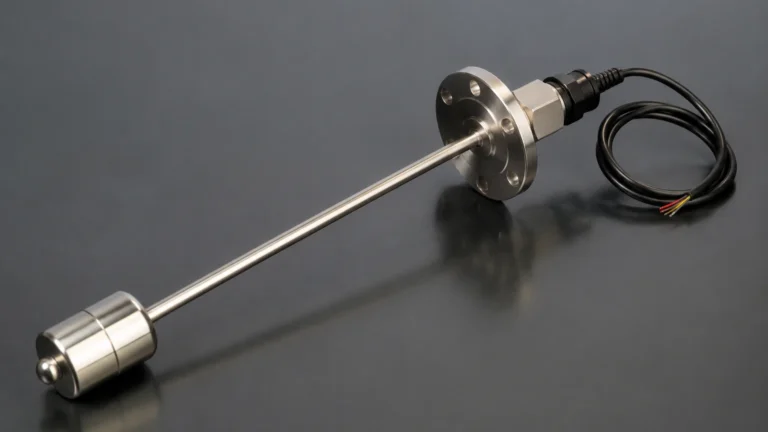
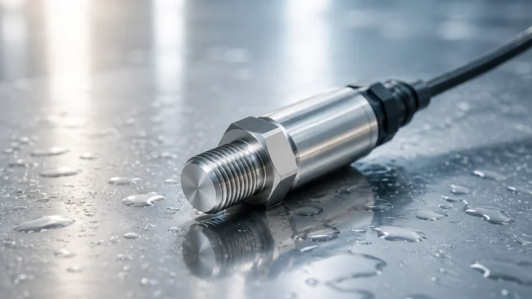
Smart Pressure Transducer
Smart Pressure Transducer
In the landscape of industrial automation and process control, the smart pressure transducer represents a significant evolution from traditional analog sensing devices. While standard transducers convert physical pressure into a basic electrical signal, smart variants integrate microprocessors to provide enhanced accuracy, digital communication capabilities, and advanced diagnostic functions. For engineers and plant managers, selecting the right pressure measurement technology is critical for ensuring safety, efficiency, and long-term reliability in applications ranging from chemical processing to municipal water management.
Understanding the Smart Pressure Transducer Principle
At its core, a pressure transducer is a device that converts mechanical pressure into an electrical signal. In industrial environments, this is typically achieved through a sensing element that deforms under pressure. The most common sensing technologies include piezoresistive, capacitive, and strain gauge sensors.
Piezoresistive Sensing
Piezoresistive sensors utilize the change in electrical resistance of a semiconductor material (usually silicon) when subjected to mechanical stress. These sensors are highly sensitive and suitable for a wide range of pressures, making them a staple in many industrial designs.
Capacitive Sensing
Capacitive transducers measure the change in electrical capacitance between a flexible diaphragm and a fixed metal plate. As pressure moves the diaphragm, the distance between the plates changes, altering the capacitance. This method is known for its high accuracy and stability, particularly in low-pressure applications.
The "Smart" Integration
What distinguishes a smart pressure transducer from its traditional counterparts is the onboard electronics. A smart device includes an Analog-to-Digital Converter (ADC), a microprocessor, and a Digital-to-Analog Converter (DAC) or a digital communication module. This architecture allows the device to:
* Perform Linearization: Correcting non-linearities inherent in the sensing element.
* Compensate for Temperature: Using internal temperature sensors to adjust pressure readings in real-time, reducing thermal drift.
* Support Digital Protocols: Communicating via HART (Highway Addressable Remote Transducer), Modbus, or PROFIBUS, allowing for remote configuration and diagnostics.
* Offer High Turndown Ratios: Enabling the user to adjust the calibrated range (e.g., 100:1) without losing significant accuracy.
Applications in Hydrostatic Level Measurement
One of the primary uses of a smart pressure transducer in industrial automation is hydrostatic level measurement. This principle relies on the fact that the pressure at the bottom of a liquid column is directly proportional to the height of the liquid and its density.
The Mathematical Foundation
The relationship is defined by the formula:
$$P = \rho \cdot g \cdot h$$
Where:
* P is the hydrostatic pressure (measured in Pascals or bar).
* ρ (rho) is the density of the liquid (kg/m³).
* g is the acceleration due to gravity (approximately 9.81 m/s²).
* h is the height of the liquid column (meters).
In a vented tank, a smart pressure transducer mounted at the base measures the pressure exerted by the liquid. Because the device is "smart," it can be programmed with the specific gravity of the fluid to output a direct level reading in meters (m) or feet (ft). For pressurized tanks, a differential pressure (DP) configuration is used, where the transducer calculates the difference between the bottom pressure and the headspace pressure to isolate the liquid level.
For more information on various level measurement technologies, you can visit our Main Page to explore radar, ultrasonic, and hydrostatic solutions.
Key Evaluation Criteria for Selection
Selecting a smart pressure transducer requires a thorough understanding of the process environment. Engineers should evaluate the following criteria to ensure optimal performance:
1. Accuracy and Stability
Industrial-grade smart transducers typically offer accuracy ratings from ±0.075% to ±0.1% of the calibrated span. It is important to distinguish between "reference accuracy" and "total probable error," which includes the effects of temperature and static pressure.
2. Pressure Range and Turndown
The nominal range of the sensor should exceed the maximum expected process pressure. However, the turndown ratio allows a single device to be calibrated for a much smaller range. For example, a sensor with a 10 bar (145 psi) range and a 100:1 turndown can be accurately calibrated to measure a 0.1 bar (1.45 psi) span.
3. Wetted Materials and Chemical Compatibility
The diaphragm and process connection must withstand the corrosive nature of the process fluid. Common materials include:
* 316L Stainless Steel: Standard for water and non-corrosive chemicals.
* Hastelloy C: Required for highly corrosive acids and chlorides.
* Tantalum: Used in extreme chemical environments.
* Ceramic: Excellent for abrasive slurries.
4. Output and Communication
While the 4-20 mA analog signal remains the industry standard, smart transducers often overlay a HART digital signal. This allows for multi-variable reporting (e.g., pressure and temperature) and remote troubleshooting using a handheld communicator or a PC-based software interface.
Installation and Commissioning Best Practices
Correct installation is as critical as device selection. Poor mounting can lead to measurement errors or premature sensor failure.
Orientation and Mounting
Pressure transducers should ideally be mounted in a location that is easily accessible for maintenance but protected from excessive vibration. In liquid applications, the sensor should be mounted below or at the same level as the process tap to prevent gas bubbles from becoming trapped in the impulse lines. Conversely, for gas applications, the sensor should be mounted above the tap to allow condensate to drain back into the process.
Atmospheric Venting
For gauge pressure measurements, the transducer requires a reference to atmospheric pressure. This is usually achieved through a vented cable (in submersible models) or a small vent port on the housing. It is vital to ensure these vents are kept clear and protected from moisture ingress using breathable desiccant filters.
Zero-Point Calibration
After installation, a "zero-trim" should be performed. Even the most accurate smart pressure transducer can show a small offset due to the mounting position or the weight of the fluid in the impulse lines. The smart electronics allow the user to reset the zero point easily via the local display or digital interface.
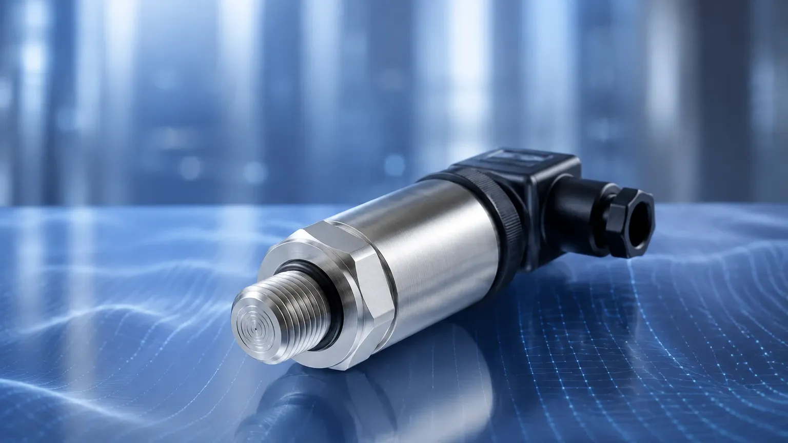
Comparison: Smart vs. Traditional Transducers
| Feature | Traditional Analog Transducer | Smart Pressure Transducer |
| :— | :— | :— |
| Signal Output | 4-20 mA or 0-10V only | 4-20 mA + HART, Modbus, or Wireless |
| Accuracy | Moderate (0.25% – 0.5%) | High (0.05% – 0.1%) |
| Configuration | Manual (Potentiometers) | Digital (Remote or Local Menu) |
| Diagnostics | None | Self-checking, error codes, sensor health |
| Temperature Compensation | Fixed/Analog | Dynamic/Digital |
| Turndown Ratio | Limited (e.g., 3:1) | Extensive (up to 100:1 or more) |
Limitations and Common Risks
Despite their advanced features, smart pressure transducers are not immune to environmental challenges.
* Overpressure Events: Exceeding the proof pressure of the sensor can permanently deform the diaphragm, leading to permanent drift or total failure. Always specify a device with a safety margin above the maximum possible surge pressure.
* Temperature Extremes: While smart devices compensate for temperature, extreme heat can damage the onboard electronics. In high-temperature steam applications, siphons or cooling towers must be used to protect the sensor.
* Clogging and Buildup: In applications involving viscous fluids or slurries, the process connection or diaphragm can become coated, leading to sluggish response times or "frozen" readings. Flush rings or diaphragm seals are often used to mitigate this risk.
* Signal Interference: Digital communication can be sensitive to Electromagnetic Interference (EMI). Ensure that shielded cabling is used and that the shield is grounded at only one end to avoid ground loops.
Frequently Asked Questions (FAQ)
Q: How often should a smart pressure transducer be calibrated?
A: While smart transducers are more stable than analog ones, most industrial standards recommend a calibration check every 1 to 2 years. However, critical safety loops may require more frequent verification.
Q: Can a smart pressure transducer measure flow?
A: Yes, when used in a differential pressure configuration across a primary flow element (like an orifice plate or Venturi tube), a smart pressure transducer can calculate the flow rate based on the square root of the pressure drop.
Q: What is the difference between a pressure transducer and a pressure transmitter?
A: In modern industrial parlance, the terms are often used interchangeably. Historically, a "transducer" referred to a device with a voltage output, while a "transmitter" referred to a device with a 4-20 mA current loop output. Smart devices are almost always classified as transmitters due to their sophisticated signal processing.
Q: Is HART communication necessary?
A: While the device will function as a standard 4-20 mA sensor without HART, having HART capability is highly recommended for easier commissioning, remote range adjustments, and accessing diagnostic data that can predict failure before it occurs.
Conclusion
The smart pressure transducer is a cornerstone of modern industrial instrumentation, providing the precision and data depth required for advanced process control. By understanding the underlying measurement principles and carefully considering factors such as chemical compatibility, turndown requirements, and installation geometry, engineers can implement solutions that offer long-term stability and reduced maintenance costs. Whether used for simple pressure monitoring or complex hydrostatic level measurement, these devices provide the critical data interface between the physical process and the digital control system.