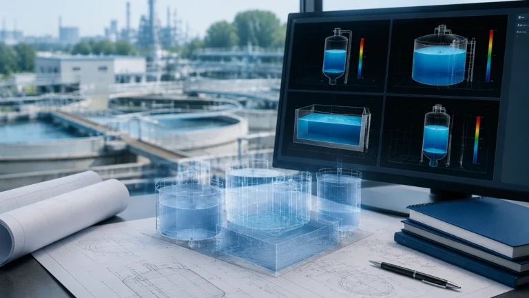
How Do Mag Meters Work
How Do Mag Meters Work
In the realm of industrial instrumentation, the electromagnetic flow meter, commonly referred to as a "mag meter," stands as one of the most versatile and reliable tools for measuring the flow of conductive liquids. Unlike mechanical flow meters that rely on moving parts like turbines or paddles, mag meters utilize the principles of physics to derive flow velocity without obstructing the fluid path. This design makes them particularly valuable in industries ranging from municipal water treatment to aggressive chemical processing.
Understanding how do mag meters work is essential for engineers and plant operators who must select the right technology for their specific application. By leveraging Faraday’s Law of Induction, these devices provide high accuracy, wide turndown ratios, and minimal maintenance requirements. As a professional manufacturer like Welk provides a variety of measurement solutions, including radar and ultrasonic sensors, the mag meter remains a cornerstone for liquid flow automation.
Understanding the Physics: Faraday’s Law of Induction
The operating principle of a magnetic flow meter is based on Faraday’s Law of Electromagnetic Induction, discovered by Michael Faraday in 1831. The law states that a voltage is induced when a conductor moves through a magnetic field.
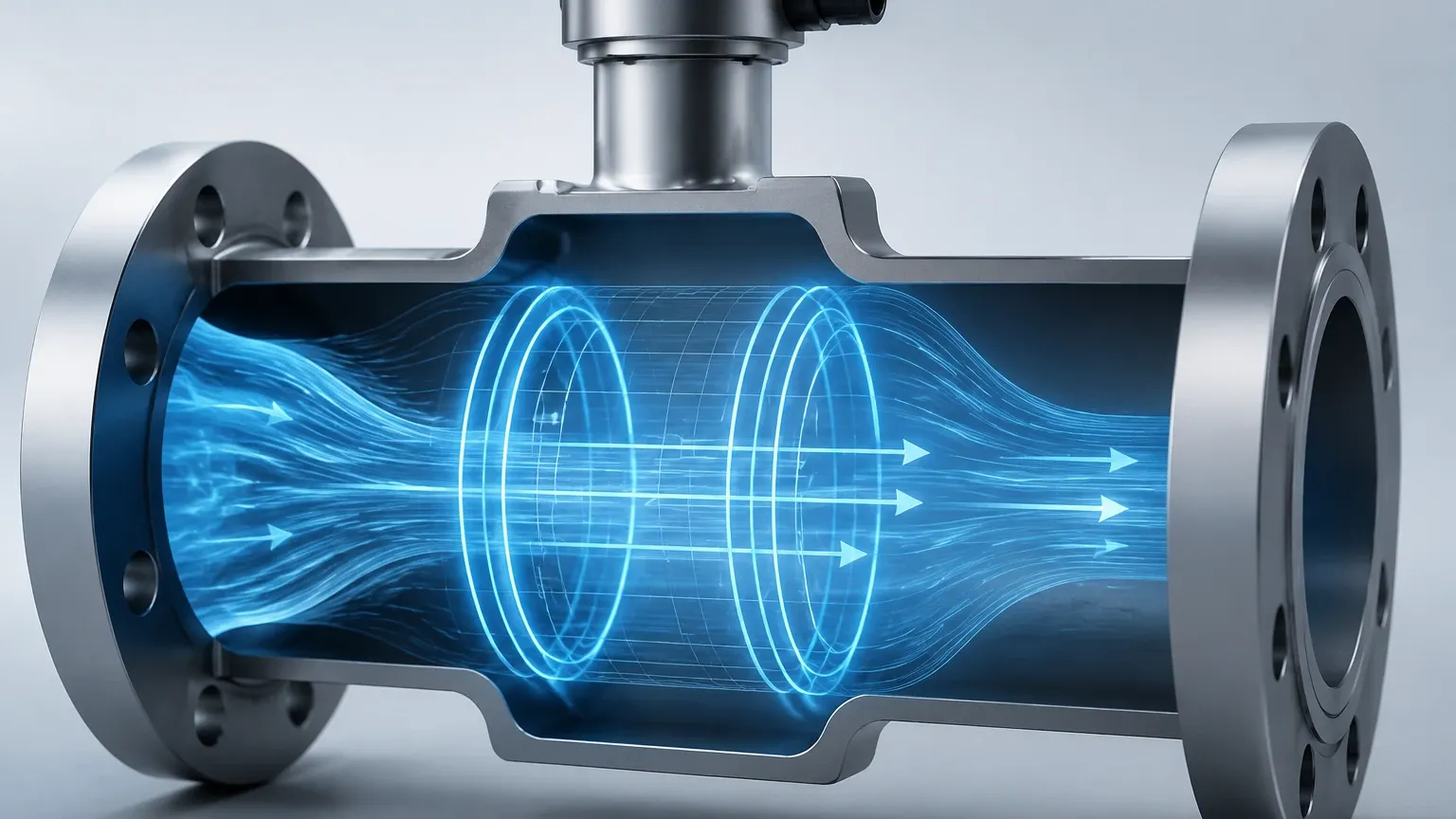
In the context of a mag meter, the "conductor" is the liquid flowing through the pipe. For the meter to function, the liquid must have a minimum level of electrical conductivity. When the conductive liquid flows through a magnetic field generated by the meter’s coils, it creates a voltage signal. This signal is directly proportional to the velocity of the liquid moving through the field.
The mathematical formula representing this principle is:
E = k × B × D × V
Where:
* E is the induced voltage (the signal generated).
* k is a constant (meter factor).
* B is the strength of the magnetic field.
* D is the distance between the electrodes (essentially the internal diameter of the pipe).
* V is the average velocity of the liquid.
Because the magnetic field strength (B) and the distance between electrodes (D) are constant for a specific meter installation, the induced voltage (E) is directly proportional to the velocity (V). The electronics within the meter’s transmitter then convert this voltage into a flow rate measurement, such as liters per minute (L/min) or cubic meters per hour (m³/h).
Core Components of an Electromagnetic Flow Meter
To understand how do mag meters work in a practical industrial setting, one must look at the physical construction of the device. A standard mag meter consists of two primary parts: the flow sensor (the part installed in the pipeline) and the transmitter (the electronics that process the signal).
1. The Flow Tube
The flow tube is the main body through which the fluid passes. It is typically constructed from non-magnetic stainless steel to ensure that the housing itself does not interfere with the magnetic field generated inside the pipe.
2. The Liner
Because the flow tube is often metal, an insulating liner is required to prevent the induced voltage from shorting out against the pipe wall. The liner material must be compatible with the process fluid. Common materials include PTFE (Teflon), PFA, and various types of rubber. The liner also protects the metal housing from corrosion and abrasion.
3. Magnetic Coils
Two electromagnetic coils are placed either outside or inside the flow tube, positioned opposite each other. When energized by the transmitter, these coils create a uniform magnetic field across the entire cross-section of the pipe.
4. Electrodes
A pair of electrodes is mounted flush with the liner, positioned perpendicular to both the flow direction and the magnetic field. These electrodes "pick up" the induced millivolt signal generated by the moving fluid and send it to the transmitter.
5. The Transmitter
The transmitter provides the current to the coils to create the magnetic field and receives the tiny voltage signal from the electrodes. It filters out noise, amplifies the signal, and converts it into a standard industrial output, such as a 4-20mA signal, pulse output, or digital communication (HART, Modbus, Profibus).
Application Engineering: Selection Criteria and Material Compatibility
Selecting the correct mag meter requires a detailed understanding of the process fluid. Since the meter relies on the fluid being a conductor, the first step is confirming conductivity. Most industrial mag meters require a minimum conductivity of 5 μS/cm (microsiemens per centimeter). This excludes most oils, pure alcohols, and deionized water.
Material Selection Table
The longevity and accuracy of a mag meter depend heavily on the materials chosen for the liner and the electrodes. The following table provides a general guideline for common industrial applications:
| Component | Material | Typical Application |
| :— | :— | :— |
| Liner | Hard Rubber | General water, wastewater, and mildly abrasive slurries. |
| | PTFE / PFA | Highly corrosive chemicals, high-temperature fluids, and food-grade processes. |
| | Polyurethane | Highly abrasive slurries like mining discharge or sand-water mixes. |
| Electrode | Stainless Steel 316L | Standard water and non-corrosive industrial liquids. |
| | Hastelloy C | Sea water, brine, and various acids. |
| | Titanium | Chlorine-based chemicals and specific oxidizing acids. |
| | Tantalum | Extremely aggressive acids like concentrated Hydrochloric or Sulfuric acid. |
When evaluating these options, engineers should also consider the pressure rating of the flanges and the temperature limits of the liner. For example, a PTFE liner can typically handle up to 180°C (356°F), whereas a standard rubber liner may be limited to 80°C (176°F).
Installation Best Practices for Accuracy
Even the most advanced mag meter will fail to provide accurate data if installed incorrectly. Because the meter measures the average velocity across the pipe, the flow profile must be stable and the pipe must be completely full.
1. Straight Pipe Runs
To ensure a laminar flow profile, mag meters generally require a minimum amount of straight pipe upstream and downstream of the sensor. A common rule of thumb is "5D and 2D"—meaning five pipe diameters of straight pipe before the meter and two diameters after. If there are high-turbulence elements like partially open valves or multiple elbows, these requirements may increase to 10D or more.
2. Ensuring a Full Pipe
Mag meters cannot accurately measure partially full pipes. The sensor should be installed in a low point of the piping system (a "U" section) or in a vertical line with the flow moving upward. This ensures that gravity keeps the pipe full and prevents air bubbles from collecting at the top of the sensor, which would cause measurement errors.
3. Proper Grounding
Grounding is perhaps the most critical and often overlooked aspect of mag meter installation. Because the signal generated is in the millivolt range, any stray electrical currents in the fluid or the piping can interfere with the reading.
* Metal Pipes: The meter should be bonded to the metal flanges of the pipe.
* Plastic or Lined Pipes: Grounding rings (thin metallic disks) must be installed between the meter and the pipe flanges to provide a path to ground for the fluid.
Limitations and Common Troubleshooting
While mag meters are robust, they are not universal solutions. Understanding their limitations is key to avoiding project failures.
* Non-Conductive Fluids: As mentioned, hydrocarbons (oil, diesel, gasoline) and ultrapure water cannot be measured with mag meters. For these applications, ultrasonic or vortex meters are often preferred.
* Entrained Air: Large bubbles or heavy aeration can cause the meter to "noise out" or provide erratic readings. If air is present, an air eliminator should be installed upstream.
* Electrode Coating: In applications involving sticky fluids or fats, a film can build up on the electrodes over time, insulating them from the fluid. Some advanced meters include "electrode cleaning" functions or use ultrasonic pulses to shed buildup.
* Vacuum Conditions: Certain liners, particularly PTFE, can collapse if the pipe is subjected to a vacuum. If vacuum conditions are possible, a reinforced liner or a different material like PFA should be specified.
For those looking to integrate flow measurement into a broader system including level control, reviewing the full technical specifications on the Main Page can help in selecting complementary technologies like radar or ultrasonic level transmitters.
Frequently Asked Questions about Mag Meter Operation
Q: Can mag meters measure the flow of gases or steam?
No. Gases and steam are not electrically conductive and do not have the density required to generate a measurable voltage signal via electromagnetic induction.
Q: Does the viscosity of the liquid affect the accuracy?
Generally, no. Mag meters are independent of viscosity, provided the flow remains relatively laminar and the fluid is conductive. This makes them excellent for thick slurries or polymers that might clog other types of meters.
Q: How often do mag meters need to be calibrated?
Because there are no moving parts to wear out, mag meters are extremely stable. In many water applications, they only require a zero-point check annually, though regulated industries (like pharmaceutical or food) may require a full wet calibration every 1-3 years.
Q: What is the minimum flow velocity required?
Most mag meters can measure velocities as low as 0.1 m/s (0.3 ft/s), but for the best accuracy, it is usually recommended to size the meter so the normal flow velocity is between 2 m/s and 5 m/s (6 ft/s to 16 ft/s).
Conclusion
Electromagnetic flow meters provide a highly accurate, low-maintenance solution for measuring conductive liquids across a vast range of industrial processes. By understanding how do mag meters work—specifically the application of Faraday’s Law and the importance of material selection and grounding—engineers can ensure long-term reliability in their automation systems. Whether managing a simple water line or a complex chemical reactor, the mag meter’s ability to provide an unobstructed, volumetric measurement makes it an indispensable tool in modern fluid handling.
For more information on industrial measurement instruments and to explore a wide range of level and flow solutions, visit the Main Page to review product options and application support.