Flow Transmitters
Flow Transmitters
In the landscape of industrial process control, flow transmitters serve as the critical bridge between physical fluid dynamics and digital automation systems. While level measurement focuses on the quantity of material within a vessel, flow measurement tracks the movement of that material through a system. For engineers and plant managers, selecting the correct flow transmitter is essential for maintaining mass balance, ensuring product quality, and optimizing energy efficiency. This guide examines the fundamental principles of flow measurement, practical selection criteria, and the technical considerations necessary for successful integration into industrial environments.
Fundamental Measurement Principles
Flow transmitters do not measure flow directly in a single, universal way. Instead, they utilize various physical laws to infer flow rates based on the properties of the fluid and the geometry of the piping. Understanding these principles is the first step in selecting a device that will remain accurate over its operational lifespan.
Differential Pressure (DP) Flow Measurement
Differential pressure is one of the most established methods in the industry. It relies on Bernoulli’s principle, which states that as the speed of a moving fluid increases, the pressure within the fluid decreases. By placing a primary element—such as an orifice plate, Venturi tube, or flow nozzle—inside the pipe, a localized pressure drop is created.
The flow transmitter measures the pressure difference between the upstream and downstream sides of the restriction. The flow rate is proportional to the square root of this differential pressure. DP meters are versatile and can handle liquids, gases, and steam, provided the fluid is relatively clean and the Reynolds number is within a predictable range.
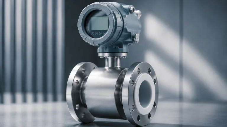
Electromagnetic Flow Measurement (Magmeters)
Electromagnetic flow transmitters operate based on Faraday’s Law of Electromagnetic Induction. This law states that a conductor moving through a magnetic field produces an electrical signal. In this application, the conductive liquid acts as the conductor.
As the fluid flows through a magnetic field generated by the transmitter’s coils, electrodes located on the pipe walls pick up a voltage proportional to the flow velocity. Because there are no moving parts and no obstructions in the flow path, magmeters are ideal for slurries and corrosive chemicals. However, they require the fluid to have a minimum conductivity, typically greater than 5 μS/cm.
Ultrasonic Flow Measurement
Ultrasonic transmitters use sound waves to determine velocity. There are two primary types:
1. Transit-Time: These devices send ultrasonic pulses diagonally across the pipe. The pulse traveling with the flow moves faster than the pulse traveling against it. The time difference is used to calculate velocity. This method is best for clean liquids.
2. Doppler: These devices reflect sound waves off particles or bubbles in the fluid. The frequency shift (Doppler effect) indicates the flow speed. This method is preferred for aerated liquids or heavy slurries.
Vortex Shedding
Vortex flow transmitters utilize the Karman Vortex Street principle. When a fluid meets a "bluff body" (a non-streamlined object) in the flow path, it creates alternating vortices on either side. The frequency at which these vortices are shed is directly proportional to the fluid velocity. Vortex meters are highly reliable for steam and low-viscosity liquids because they are not affected by changes in pressure or temperature.
Coriolis Mass Flow
Unlike the methods above, which measure volumetric flow, Coriolis transmitters measure mass flow directly. They use the Coriolis effect, where a vibrating tube experiences a twist as fluid moves through it. The amount of twist is proportional to the mass flow rate. These are the most accurate (and often most expensive) transmitters, capable of measuring mass, density, and temperature simultaneously.
Practical Selection Table
Choosing the right technology requires balancing fluid characteristics against performance requirements. The following table provides a general comparison for common industrial applications.
| Technology | Fluid Type | Typical Accuracy | Pressure Drop | Primary Advantage |
| :— | :— | :— | :— | :— |
| Differential Pressure | Liquid, Gas, Steam | ±0.5% to ±2% | Medium to High | Low cost, well-understood |
| Electromagnetic | Conductive Liquids | ±0.25% to ±0.5% | None | No moving parts, handles slurries |
| Ultrasonic | Clean or Aerated Liquids | ±0.5% to ±2% | None | Non-intrusive (clamp-on options) |
| Vortex | Low-viscosity Liquid, Steam | ±1% | Medium | Excellent for high-temp steam |
| Coriolis | Liquids and Gases | ±0.1% | Medium | Direct mass flow measurement |
Relationship Between Flow and Level Measurement
In many process plants, flow and level measurement are used in tandem to provide a complete picture of the inventory and process efficiency. For example, in open channel flow (such as wastewater treatment), a level sensor—like those provided by Welk—is used to measure the height of water passing over a weir or through a flume. This level reading is then converted into a flow rate using standardized mathematical formulas.
Furthermore, in tank farm management, flow transmitters monitor the "inflow" and "outflow," while level transmitters provide the "static inventory" check. Discrepancies between the integrated flow data and the level change can indicate leaks, evaporation, or calibration errors. For those looking to integrate these systems, you can Review product options and application support on the Welk Main Page to see how various measurement technologies complement one another.
Installation Considerations
The accuracy of a flow transmitter is heavily dependent on its installation. Even the most expensive Coriolis meter will fail to perform if the flow profile is disturbed.
Straight Pipe Runs
Most flow measurement technologies require a specific length of straight pipe upstream and downstream of the sensor. This ensures a "fully developed" laminar flow profile. Typically, a minimum of 10 pipe diameters (10D) upstream and 5 pipe diameters (5D) downstream is required. If elbows, valves, or pumps are close to the transmitter, these requirements may increase to 20D or 30D.
Orientation and Mounting
* Liquid Service: The pipe must always be full. Transmitters should ideally be installed in vertical upward-flowing pipes or at the lowest point of a horizontal run to prevent air pockets.
* Gas Service: Transmitters should be installed at the high points of a system to prevent moisture or condensate from collecting in the sensor.
* Grounding: For electromagnetic flow meters, proper grounding is non-negotiable. The fluid, the sensor, and the transmitter housing must be at the same electrical potential to prevent stray currents from interfering with the low-voltage measurement signal.
Environmental Factors
Industrial environments often involve vibration, electromagnetic interference (EMI), and extreme temperatures. Ensure that the transmitter housing (e.g., IP67 or NEMA 4X) is rated for the environment and that signal cables are shielded and separated from high-voltage power lines.

Limitations and Common Risks
While modern flow transmitters are robust, they are not infallible. Engineers should be aware of the following risks:
1. Cavitation and Flashing: In liquid applications, if the pressure drops below the vapor pressure of the fluid, bubbles will form (cavitation). This causes significant measurement errors and can physically erode the sensor internal components.
2. Scaling and Coating: In chemical or wastewater applications, material may build up on the electrodes of a magmeter or the bluff body of a vortex meter. This changes the geometry of the flow path and degrades accuracy over time.
3. Minimum Flow Rates (Turndown Ratio): Every transmitter has a "low-flow cut-off." Below a certain velocity, the signal becomes too noisy to be reliable. It is crucial to size the meter for the actual flow range, not just the pipe size.
4. Fluid Properties: Changes in viscosity or density can affect DP and vortex meters. If the process fluid changes significantly, the transmitter may require recalibration or a compensation algorithm (e.g., using temperature and pressure inputs).
Frequently Asked Questions (FAQs)
Q: How often should a flow transmitter be calibrated?
A: Calibration frequency depends on the criticality of the process and the stability of the fluid. For custody transfer or high-value chemical dosing, annual calibration is standard. For general process monitoring, every 2 to 3 years may suffice, provided there are no signs of drift.
Q: Can I use a flow transmitter designed for water on oil?
A: It depends on the technology. A magmeter will not work on oil because oil is non-conductive. An ultrasonic or Coriolis meter will work, but the different viscosity and sound speed of oil must be programmed into the transmitter settings.
Q: What is the difference between a flow sensor and a flow transmitter?
A: The sensor (or primary element) is the part that physically interacts with the fluid. The transmitter is the electronic component that interprets the sensor's signal and converts it into a standardized output like 4-20mA, Modbus, or Foundation Fieldbus.
Q: How do I handle flow measurement in pipes that are not always full?
A: Standard flow transmitters require a full pipe to maintain accuracy. If the pipe is partially full, you must treat it as an open channel application, using a level sensor (such as radar or ultrasonic) in conjunction with a flume or weir.
Conclusion
Flow transmitters are indispensable tools for modern industrial automation. By understanding the underlying physics—whether it be differential pressure, electromagnetics, or ultrasonics—engineers can select a device that provides reliable data for years. Successful implementation requires more than just purchasing a high-quality sensor; it demands careful attention to installation geometry, fluid compatibility, and integration with other process variables like level and pressure. For comprehensive solutions in industrial measurement, professionals should always verify that their chosen instrumentation aligns with the specific chemical and physical demands of their unique application.