Inline Ph Sensor
Inline Ph Sensor
In industrial process control, the accurate measurement of hydrogen ion activity—commonly known as pH—is essential for ensuring product quality, protecting equipment from corrosion, and meeting environmental compliance standards. While laboratory testing provides high precision, the delay between sampling and results often makes it unsuitable for dynamic processes. This is where the inline pH sensor becomes a critical component of the automation architecture. By providing real-time, continuous data directly from the process stream, these sensors allow for immediate adjustments in chemical dosing, neutralization, and fermentation processes.
For engineers and plant operators, selecting an inline pH sensor requires an understanding of electrochemical principles, the physical constraints of the piping system, and the specific chemical environment of the application. This guide provides a technical overview of inline pH measurement technology, selection criteria, and installation best practices to ensure long-term reliability in demanding industrial environments.
Fundamental Principles of pH Measurement
To effectively implement an inline pH sensor, it is necessary to understand the underlying potentiometric measurement principle. Most industrial pH sensors operate as a battery where the voltage produced is proportional to the hydrogen ion concentration of the solution.
The Nernst Equation
The relationship between the measured potential and the pH value is governed by the Nernst Equation. In a typical setup, a pH-sensitive glass membrane develops a millivolt (mV) potential when in contact with a liquid. At a neutral pH of 7.0 and a temperature of 25°C (77°F), the theoretical potential is 0 mV. As the solution becomes more acidic (lower pH), the potential increases positively; as it becomes more alkaline (higher pH), the potential increases negatively. The theoretical change is approximately 59.16 mV per pH unit.
Electrode Components
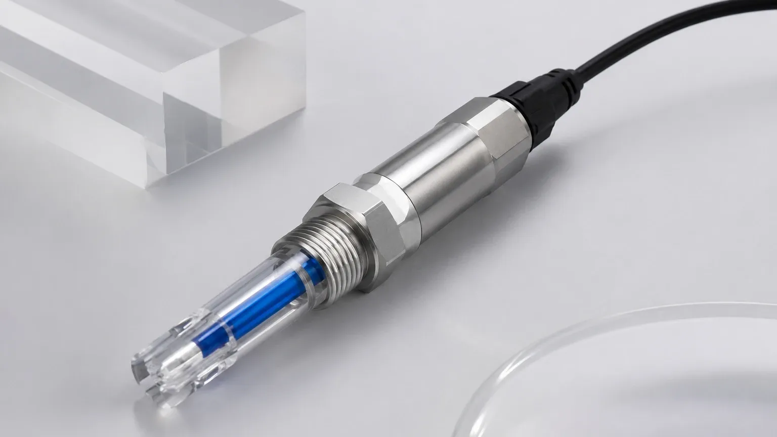
A complete inline pH sensor assembly generally consists of two primary elements, often combined into a single "combination electrode":
1. Measuring Electrode: Features a specialized glass bulb sensitive to hydrogen ions.
2. Reference Electrode: Provides a stable, constant potential against which the measuring electrode is compared. This is usually achieved through a silver/silver chloride (Ag/AgCl) internal element submerged in a potassium chloride (KCl) electrolyte.
3. Reference Junction: A porous plug (made of ceramic, PTFE, or wood) that allows electrical contact between the internal electrolyte and the process liquid while minimizing the mixing of the two.
Components of an Inline pH Measurement System
An inline pH sensor does not operate in isolation. It is part of a loop that translates a delicate electrochemical signal into actionable industrial data. The system typically includes:
* The Sensor (Probe): The primary sensing element that contacts the fluid.
* The Housing or Fitting: The mechanical interface that secures the sensor into a pipe or tank. This may include retractable assemblies that allow the sensor to be removed for maintenance without stopping the process flow.
* The Cable: High-impedance cabling is required to transmit the low-voltage signal to the transmitter. Because the signal is weak, cable length and shielding are critical to prevent electromagnetic interference.
* The Transmitter/Analyzer: This device amplifies the mV signal, performs temperature compensation, and converts the data into a standard industrial output, such as 4-20mA, Modbus, or HART. For comprehensive facility management, these systems are often integrated with other process instruments available on the Main Page of industrial instrumentation providers.
Selecting the Right Inline pH Sensor for Industrial Applications
Choosing a sensor involves balancing the chemical requirements of the process with the physical durability of the instrument. No single sensor design is universal. Below is a selection matrix based on common industrial challenges:
| Process Condition | Recommended Sensor Feature | Rationale |
| :— | :— | :— |
| High Solids / Slurries | Flat surface glass or Open junction | Minimizes clogging and physical abrasion of the glass bulb. |
| High Pressure (>5 bar / 72 psi) | Pressurized reference or Solid polymer electrolyte | Prevents process fluid from forcing its way into the reference electrode. |
| Pure Water (Low Conductivity) | Refillable liquid electrolyte | Ensures a stable electrical path when ions are scarce in the process fluid. |
| Chemicals (HF Acid) | HF-resistant glass | Standard glass membranes dissolve rapidly in hydrofluoric acid. |
| Pharmaceutical / Food | Hygienic (EHEDG/3A) design | Ensures the sensor can be sterilized (CIP/SIP) without harboring bacteria. |
| High Temperature (>80°C / 176°F) | High-temperature glass formulation | Prevents rapid aging and "drifting" of the glass membrane potential. |
Glass vs. Non-Glass (ISFET)
While glass electrodes are the industry standard, Ion-Sensitive Field Effect Transistor (ISFET) sensors are an alternative for applications where glass breakage is a safety risk (e.g., food production). ISFET sensors use a silicon chip to measure pH, making them more robust, though they can be more sensitive to electrical noise.
Installation Requirements and Mounting Configurations
The physical placement of an inline pH sensor significantly impacts its lifespan and accuracy. Unlike a level meter that might be mounted at the top of a tank, a pH sensor must be constantly submerged in the process liquid.
Mounting Angles
Standard glass pH sensors should never be installed horizontally or upside down. They must typically be mounted at least 15° above the horizontal plane. This ensures that the internal filling solution stays in contact with the glass bulb and that any air bubbles inside the electrode float away from the sensing tip.
Flow Considerations
* Velocity: High flow velocities (above 2-3 meters per second) can cause a "streaming potential," which adds noise to the pH reading. It can also cause physical erosion of the sensor.
* Turbulence: Sensors should be placed in areas with steady flow. Avoid placing them immediately after a pump or a 90-degree bend where cavitation or extreme turbulence may occur.
* Bypass Loops: In many large-diameter pipes, it is preferable to install the inline pH sensor in a smaller bypass loop (sample line). This allows for easier isolation, calibration, and cleaning without interrupting the main process flow.
Pipe Diameter and Immersion Depth
The sensor bulb must be positioned in the center of the flow profile to get a representative sample. In small pipes (e.g., DN25 or 1-inch), T-pieces must be sized correctly to ensure the sensor does not block the flow or hit the opposite wall of the pipe.
Operational Limitations and Environmental Factors
Every inline pH sensor has a finite lifespan, typically ranging from a few months to two years, depending on the severity of the application. Several factors can accelerate sensor failure:
1. Temperature Extremes: High temperatures accelerate the chemical aging of the glass membrane. Conversely, rapid temperature fluctuations (thermal shock) can crack the glass.
2. Coating and Fouling: In wastewater or oil-heavy processes, substances can coat the glass or clog the reference junction. This leads to slow response times and sluggish readings. Automatic cleaning systems (ultrasonic or water spray) may be required.
3. Chemical Attack: Strong bases (high pH) can slowly dissolve the glass membrane over time, while certain solvents can attack the sensor’s seals or body material (typically Ryton, PVDF, or Stainless Steel).
4. Ground Loops: If the process liquid is not properly grounded or if there are electrical leaks from motors/pumps, stray currents can interfere with the high-impedance pH signal, causing erratic readings.
Maintenance, Calibration, and Troubleshooting
Because pH is an electrochemical measurement, the sensor's output will naturally drift over time as the glass membrane ages and the reference electrolyte is depleted. Regular maintenance is not optional.
Calibration Procedure
Calibration should be performed using at least two buffer solutions (typically pH 4.0, 7.0, or 10.0) that bracket the expected process range.
* Zero Point (Offset): Usually checked at pH 7.0. A healthy sensor should be within ±30 mV of the theoretical zero.
* Slope: Checked with a second buffer. The slope represents the efficiency of the sensor. A new sensor has a slope near 100% (59.16 mV/pH). If the slope drops below 85% or 80%, the sensor usually requires replacement.
Cleaning Protocols
If a sensor becomes sluggish, it may be fouled. Cleaning agents should be chosen based on the contaminant:
* Grease/Oils: Mild detergent or isopropyl alcohol.
* Mineral Scale: 5% Hydrochloric acid (HCl).
* Proteins: Pepsin in HCl solution.
The Role of pH Monitoring in Integrated Process Control
In many industrial settings, pH measurement is closely tied to other fluid parameters. For instance, in a chemical neutralization tank, the inline pH sensor dictates the rate of acid or base injection, while level measurement instruments—such as those found at Welk—ensure the tank does not overflow during the dosing process.
In water treatment, monitoring the pH inline is essential for the effectiveness of flocculation and disinfection. If the pH is outside the optimal range, the chemical reactions required to remove contaminants will not occur efficiently, regardless of the liquid level or flow rate. Therefore, integrating pH data with level and flow data provides a holistic view of the process, enabling higher safety standards and operational efficiency.
Frequently Asked Questions (FAQ)
Q: How often should I calibrate my inline pH sensor?
A: The frequency depends on the process. In stable, clean water applications, monthly calibration may suffice. In aggressive chemical processes or wastewater, weekly or even daily checks may be necessary.
Q: Can I use a standard pH sensor in deionized (DI) water?
A: Standard sensors often fail or drift in DI water because the low conductivity makes it difficult for the electrical circuit to complete. You should use a sensor specifically designed for low-conductivity water, which usually features a high-flow reference junction.
Q: What is the maximum distance I can run a cable from the sensor to the transmitter?
A: For analog sensors without an internal pre-amplifier, the limit is typically 10 to 15 meters (33 to 49 feet). Beyond this, the signal degrades significantly. Digital sensors or sensors with integrated pre-amplifiers can transmit signals over much longer distances (up to 100 meters or more).
Q: Why does my pH reading change when the temperature changes?
A: Temperature affects pH in two ways: it changes the chemical equilibrium of the solution itself and it changes the sensitivity of the glass electrode (the Nernstian slope). Most modern transmitters use an Automatic Temperature Compensation (ATC) probe to correct for the electrode's change in sensitivity, but they do not "correct" the actual chemical shift of the liquid.
Q: How should I store a pH sensor when it is not in use?
A: Never store a pH sensor in deionized water or dry. It should be stored in a specialized storage solution (usually 3M or 4M KCl) or a pH 4.0 buffer to keep the glass membrane hydrated and the reference junction active.