Coriolis Mass Flow Meter Working
Coriolis Mass Flow Meter Working
In the landscape of industrial process control, the ability to measure mass directly rather than calculating it from volume and density is a significant advantage. Coriolis mass flow meters have become the gold standard for high-precision applications in chemical processing, oil and gas, and food production. Understanding the Coriolis mass flow meter working principle is essential for engineers and plant managers who require high accuracy and low maintenance in their fluid handling systems.
Unlike volumetric flow meters, which are sensitive to changes in temperature, pressure, and viscosity, a Coriolis meter measures mass flow directly. This article provides a comprehensive technical overview of how these instruments function, their design variations, and the practical considerations for their implementation in industrial environments.
The Fundamental Principle: The Coriolis Effect
To understand Coriolis mass flow meter working, one must first understand the physics of the Coriolis effect. The effect describes the inertial force acting on an object that is in motion within a frame of reference that is rotating.
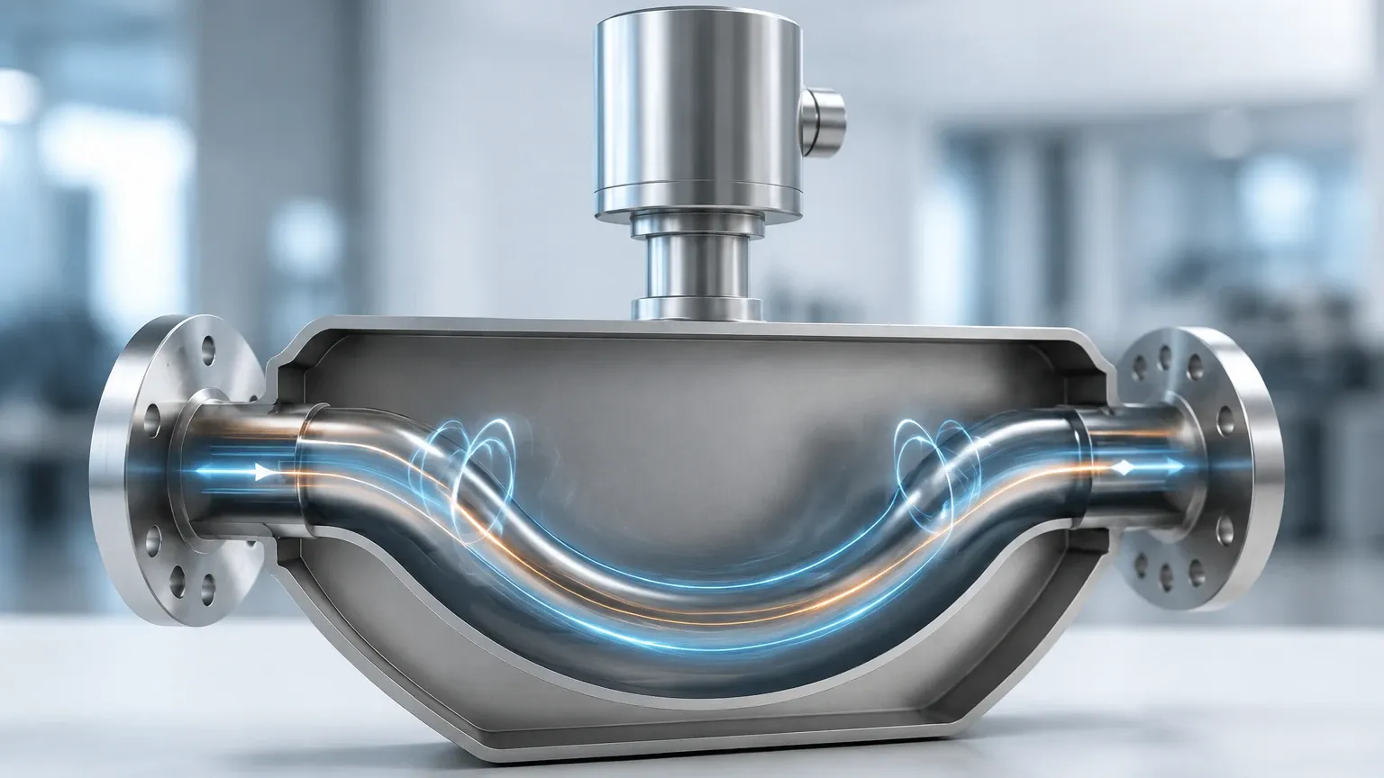
In an industrial flow meter, this rotation is replaced by high-frequency vibration. The meter consists of one or more vibrating tubes. When a fluid (liquid or gas) flows through these tubes, the mass of the fluid moving through the vibration causes the tubes to twist or distort. This distortion is the physical manifestation of the Coriolis force.
The Mechanics of Oscillation
The meter’s internal tubes are driven to oscillate at their resonant frequency by an electromagnetic drive coil. When there is no flow, the tubes vibrate in a uniform, symmetrical manner. Sensors (pick-offs) located at the inlet and outlet sides of the tube record the vibration cycle. In a no-flow state, the sine waves recorded by the inlet and outlet sensors are perfectly in phase.
As soon as fluid begins to flow, the Coriolis force is generated. This force acts in opposite directions on the inlet and outlet sides of the vibrating tube:
1. At the Inlet: The fluid resists being moved upward or downward by the tube's vibration, creating a force that opposes the motion.
2. At the Outlet: The fluid, having already gained momentum from the vibration, resists slowing down, creating a force that assists the motion.
This opposition of forces causes the tube to twist. This twisting motion results in a phase shift between the inlet and outlet sensors.
Calculating Mass Flow from Phase Shift
The time delay ($Δt$) between the sine waves detected by the pick-off sensors is directly proportional to the mass flow rate. Modern transmitters process this high-frequency signal to provide an instantaneous mass flow reading. Because the measurement is based on inertia and time, it remains independent of the fluid's physical properties, such as density or viscosity changes.
Simultaneous Density and Temperature Measurement
A unique aspect of Coriolis mass flow meter working is the ability to provide multi-variable data. Beyond mass flow, these meters typically provide density and temperature readings.
* Density Measurement: The resonant frequency at which the tubes vibrate depends on the total mass of the tube and the fluid inside it. Since the volume of the tube is fixed, a change in the fluid's density changes the total mass, which in turn changes the vibration frequency. By measuring this frequency, the meter can calculate the fluid's density in real-time.
* Temperature Measurement: To compensate for the slight changes in tube elasticity caused by thermal expansion or contraction, a Resistance Temperature Detector (RTD) is mounted on the tube. This temperature data is also made available as a process output.
Key Components of a Coriolis Meter
To ensure reliable operation in harsh industrial environments, the internal components are engineered for durability and precision.
| Component | Function |
| :— | :— |
| Flow Tubes | The primary sensing element, usually made of stainless steel, Hastelloy, or Titanium. |
| Drive Coil | An electromagnetic assembly that maintains the tube's oscillation at its resonant frequency. |
| Pick-off Sensors | Electromagnetic sensors that detect the position and velocity of the tubes to measure phase shift. |
| Transmitter | The electronics package that powers the drive coil, processes sensor signals, and provides outputs (4-20mA, HART, Modbus). |
| Case/Housing | A secondary containment vessel that protects the internal components and provides safety in case of tube failure. |
Practical Selection: Tube Geometry
When evaluating Coriolis mass flow meter working for a specific application, the geometry of the flow tubes is a critical factor. There are two primary designs: Curved (U-shaped) and Straight-tube.
Curved Tube Designs
Curved tubes are highly sensitive because the geometry amplifies the Coriolis effect. They are ideal for low-flow applications or where extremely high accuracy is required. However, they tend to have a larger physical footprint and can cause a higher pressure drop across the meter.
Straight Tube Designs
Straight tubes are easier to clean and are often preferred in the food and beverage industry (sanitary applications) or for fluids that tend to coat or clog. They have a lower pressure drop and are more compact, but they require more sophisticated electronics to detect the smaller phase shifts generated in a straight path.
Technical Selection Criteria
Selecting the right meter requires a balance between process requirements and instrument capabilities. Engineers should consult the Main Page of technical providers to compare specific model specifications against their application needs.
1. Mass Flow Range: Ensure the minimum and maximum expected flow rates fall within the meter's optimal accuracy band.
2. Pressure Drop: Calculate the allowable pressure loss. High-viscosity fluids in U-shaped meters may cause significant drops.
3. Material Compatibility: The wetted parts must be compatible with the process fluid to prevent corrosion or erosion.
4. Accuracy Requirements: Most Coriolis meters offer accuracy between 0.1% and 0.05% for liquids, though gas measurement accuracy is typically lower (around 0.5%).
Installation Considerations and Best Practices
While Coriolis meters are robust, their reliance on precision vibration makes them sensitive to certain installation factors. Proper mounting is essential for maintaining the integrity of the Coriolis mass flow meter working principle.
Vibration Isolation
External mechanical vibrations from pumps or heavy machinery can interfere with the meter’s internal oscillation. It is recommended to use robust piping supports on both the upstream and downstream sides of the meter to isolate it from plant noise.
Avoiding Entrained Gas
In liquid applications, the presence of air bubbles (slug flow) can significantly disrupt the measurement. The gas phase has a much lower density, which causes the tubes to vibrate erratically. If gas entrainment is possible, the meter should be installed in a vertical pipe with upward flow to help bubbles pass through quickly, or air eliminators should be used upstream.
Zero Calibration
Upon installation and under full-pipe, no-flow conditions, a "zero trim" should be performed. This accounts for the specific mechanical stresses of the piping installation and ensures that the phase shift is exactly zero when there is no flow.
Limitations and Risks
Despite their versatility, Coriolis meters are not a universal solution for every process.
* Initial Cost: The complexity of the sensor and the materials used make Coriolis meters more expensive upfront than electromagnetic or vortex meters.
* Size Constraints: Large-diameter Coriolis meters (above 10 inches or 250mm) become extremely heavy and expensive, often making them impractical for high-volume water transport.
* Gas Sensitivity: While they can measure gas, the low mass of gases results in a very small Coriolis force, which reduces the signal-to-noise ratio and overall accuracy compared to liquid measurements.
Integration with Level Measurement Systems
In many industrial setups, mass flow data is used in conjunction with level measurement to provide a complete picture of inventory and process efficiency. For instance, in a blending tank, radar or ultrasonic level sensors provide the volume-based inventory, while Coriolis meters provide the precise mass of ingredients being added. This dual-verification system is critical for high-value chemical production where mass balance is the primary metric for quality control.
By integrating reliable flow data with advanced level instruments, facilities can achieve a higher degree of automation and reduce the risk of overfills or batch inconsistencies. For those managing complex tank farms or processing plants, reviewing the full range of instrumentation on the Main Page of a specialized manufacturer can help identify the best combination of technologies.
Frequently Asked Questions
Q: Can Coriolis meters measure bidirectional flow?
A: Yes, the phase shift simply reverses direction. The transmitter can be configured to show forward flow, reverse flow, or net totals.
Q: Do Coriolis meters require straight run piping?
A: Unlike turbine or ultrasonic (transit-time) meters, Coriolis meters are generally not sensitive to flow profile distortions. Therefore, they do not require long straight runs of pipe before or after the meter, making them ideal for tight skid-mounted systems.
Q: How often do they need recalibration?
A: Because there are no moving parts that wear out (like bearings in a turbine meter), the calibration is exceptionally stable. Most users only perform a zero-point check periodically, with full factory recalibration required only for regulated custody transfer applications.
Conclusion
The Coriolis mass flow meter working principle offers a level of precision and multi-variable data that few other technologies can match. By measuring mass, density, and temperature in a single device, these meters simplify process loops and improve the accuracy of mass balance calculations. While the initial investment is higher, the reduction in maintenance and the elimination of secondary compensation sensors often result in a lower total cost of ownership over the life of the instrument. When paired with high-quality level measurement solutions, Coriolis meters provide the foundational data necessary for modern, efficient industrial automation.