Radar Level Sensor Ic
Understanding Radar Level Sensor IC Technology in Industrial Instrumentation
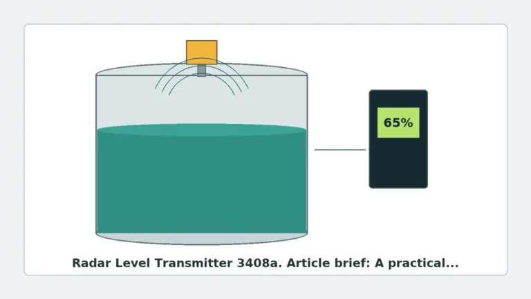
The evolution of industrial level measurement has been defined by a shift from mechanical contact methods to highly precise non-contact electronic solutions. At the heart of this technological leap is the radar level sensor ic, a semiconductor component that has revolutionized the design and performance of modern Radar Level Meters. For engineers and procurement specialists, understanding the underlying IC technology is essential for selecting instrumentation that meets the rigorous demands of chemical processing, water treatment, and bulk solids management.
In contemporary industrial design, the transition from discrete microwave components to Monolithic Microwave Integrated Circuits (MMICs) has allowed manufacturers like Welk to produce sensors that are smaller, more energy-efficient, and significantly more accurate. This guide explores the engineering principles, selection criteria, and practical application of radar technology in level measurement.
Measurement Principles: From Signal Generation to Data Output
Before selecting a specific instrument, it is critical to understand how a radar level sensor ic processes information. Industrial radar meters generally utilize one of two primary measurement principles: Pulse Radar or Frequency Modulated Continuous Wave (FMCW).
Pulse Radar (Time of Flight)
Pulse radar functions by emitting short microwave pulses toward the medium. The sensor measures the time it takes for the pulse to travel to the surface and return to the antenna. This "Time of Flight" (ToF) is directly proportional to the distance. While energy-efficient, pulse radar often struggles with low-dielectric materials and turbulent surfaces compared to modern FMCW alternatives.
Frequency Modulated Continuous Wave (FMCW)
Most high-performance radar level sensor ic designs today utilize FMCW technology. In this method, the transmitter emits a continuous signal with a constantly changing frequency (a frequency sweep). When the reflected signal is received, it is compared against the signal being transmitted at that exact moment. The frequency difference (the "beat frequency") is proportional to the distance to the material surface.
FMCW offers several advantages in industrial environments:
* Superior Signal-to-Noise Ratio: Better performance in dusty or steamy conditions.
* Higher Accuracy: Capability to measure within ±1 mm to ±2 mm tolerances.
* Better Resolution: Ability to distinguish between the material surface and tank obstructions like agitators.
The Role of Frequency: 24GHz vs. 80GHz ICs
The operating frequency of the radar level sensor ic dictates the beam angle and the physical size of the antenna. In the B2B industrial sector, the market has largely bifurcated into 24GHz and 80GHz solutions.
| Feature | 24GHz Radar Sensors | 80GHz Radar Sensors |
| :— | :— | :— |
| Beam Angle | Wide (approx. 10° to 30°) | Narrow (approx. 3° to 8°) |
| Antenna Size | Larger (typically 50mm – 100mm) | Compact (typically 20mm – 40mm) |
| Sensitivity | Moderate | High (better for low dielectric liquids) |
| Dust/Steam Penetration | Excellent | Good (but beam can be scattered by heavy rain) |
| Application Focus | Large silos, simple storage tanks | Narrow nozzles, tanks with internal obstacles |
Selecting an 80GHz radar level sensor ic allows for a narrower beam, which is vital when installing sensors in tanks with internal heating coils, ladders, or agitators. The narrow beam avoids these obstructions, reducing the need for complex false-echo suppression software.
Technical Selection Criteria for Industrial Applications
When evaluating Radar Level Meters for a specific project, engineers must look beyond the IC itself and consider the integrated system's performance characteristics.
1. Dielectric Constant ($ε_r$)
The dielectric constant of the medium is the most significant factor in signal reflection. Materials with high $ε_r$ (e.g., water, $ε_r ≈ 80$) reflect signals strongly. Hydrocarbons and dry solids often have low $ε_r$ values (1.4 to 2.5), requiring a radar level sensor ic with high dynamic range and sensitivity to detect the weak return signal.
2. Measurement Range and Accuracy
Industrial silos may reach heights of 30 meters to 100 meters. The IC must be capable of maintaining signal integrity over these distances. For high-precision applications, such as custody transfer in oil and gas, 80GHz FMCW sensors are typically preferred for their millimeter-level accuracy.
3. Process Conditions (Pressure and Temperature)
While the radar level sensor ic is protected within the housing, the antenna and seal (typically PTFE or PEEK) must withstand the process environment. Standard industrial units handle temperatures from -40°C to +200°C and pressures up to 40 bar (4 MPa), though specialized high-temperature versions are available.
Installation and Engineering Considerations
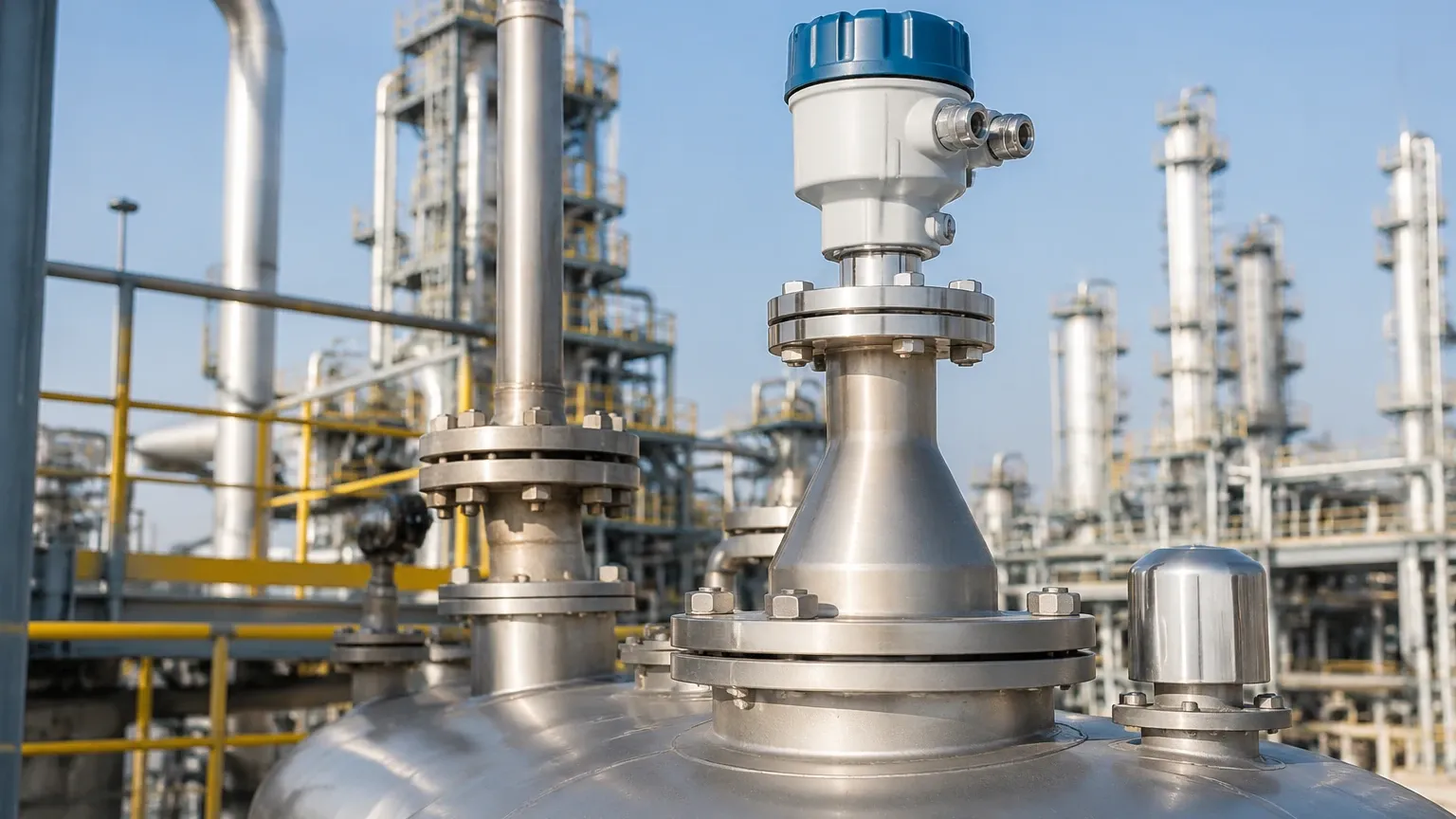
Proper installation is as critical as the choice of IC technology. Even the most advanced radar level sensor ic will fail to provide accurate data if the mounting geometry is incorrect.
Nozzle Geometry
The mounting nozzle should be as short as possible. If the nozzle is too long or narrow, it can create internal reflections (ringing) that interfere with the measurement, especially near the top of the tank. This area is known as the "Blind Zone" or "Dead Band."
Obstructions and False Echoes
In vessels with agitators or support struts, the sensor should be positioned so that the signal beam does not strike these objects. If contact is unavoidable, modern Radar Level Meters include software algorithms for "False Echo Mapping," where the sensor learns the fixed reflections within the empty tank and ignores them during operation.
Orientation and Polarization
Radar waves are polarized. Rotating the sensor slightly during installation can sometimes minimize reflections from the tank walls. Most industrial sensors include a marking on the housing to indicate the polarization plane for alignment.
Limitations and Risk Mitigation
Despite their versatility, radar sensors have specific limitations that engineers must account for:
1. Heavy Foam: Extremely thick, dense foam can absorb the radar signal entirely, leading to a "Loss of Echo" (LoE) error. In these cases, a guided wave radar or a hydrostatic transmitter may be more appropriate.
2. Vacuum Conditions: While radar works in a vacuum (unlike ultrasonic sensors which require a medium for sound travel), the seal integrity of the sensor housing becomes the primary concern.
3. Condensation and Buildup: While 80GHz sensors handle buildup better than older models, significant crystalline buildup on the antenna lens can attenuate the signal. Integrated air purge systems are often used to keep the lens clean in dusty environments.
Buyer’s Checklist for International Procurement
When sourcing equipment from a manufacturer like Welk, international buyers should confirm the following technical specifications to ensure compatibility and reliability:
* Signal Output: Does the unit support 4-20mA with HART, Modbus RS485, or Profibus?
* Certifications: Are ATEX, IECEx, or SIL2 certifications required for hazardous zones?
* Housing Material: Is the housing aluminum or stainless steel (316L) for corrosive coastal or chemical environments?
* Process Connection: Are the flange sizes (DN80, DN100, etc.) or thread types (G1½, NPT) compatible with existing tank ports?
Frequently Asked Questions (FAQ)
Q: Can a radar level sensor ic measure the interface between two liquids?
A: Generally, non-contact radar is used for the top surface level. For interface measurement (e.g., oil over water), Guided Wave Radar (GWR) is typically required, as the probe allows the signal to penetrate the top layer and reflect off the interface.
Q: How does the radar level sensor ic handle turbulent surfaces?
A: FMCW ICs use sophisticated digital signal processing (DSP) to average the reflections from a turbulent surface, providing a stable averaged level reading rather than a fluctuating one.
Q: What is the power consumption of these sensors?
A: Most modern industrial radar meters are loop-powered (2-wire), operating on 24V DC and consuming less than 22mA. This makes them ideal for integration into existing PLC/DCS loops.
Q: Is 80GHz always better than 24GHz?
A: Not necessarily. While 80GHz offers better precision and smaller beams, 24GHz is often more robust in extremely dusty environments (like cement silos) where the longer wavelength can better penetrate heavy particulate clouds.
Conclusion
The integration of advanced radar level sensor ic technology into industrial Radar Level Meters has provided the process industry with unprecedented reliability. By understanding the frequency trade-offs, the impact of dielectric constants, and the necessity of precise installation, engineering teams can implement level measurement solutions that minimize maintenance and maximize process uptime. Whether managing water treatment facilities or complex chemical reactors, the right radar technology serves as a foundation for effective industrial automation.