Radar Level Sensor Installation
Radar Level Sensor Installation: A Technical Engineering Guide
In modern industrial process automation, the accuracy of inventory management and process control depends heavily on the reliability of level instrumentation. Among the various technologies available, Radar Level Meters have emerged as the preferred solution for challenging environments involving high temperatures, corrosive chemicals, and varying pressures. However, the performance of these instruments is not solely dependent on the electronics; the physical radar level sensor installation plays a critical role in signal integrity and measurement accuracy.
This guide provides a comprehensive technical overview of radar measurement principles, selection criteria, and the engineering best practices required for successful installation in industrial tanks and silos.
Understanding Radar Measurement Principles
Before proceeding with installation, engineers must understand how radar sensors interact with the process environment. Radar level transmitters utilize electromagnetic waves, typically in the microwave spectrum, to measure the distance from the sensor to the surface of the medium.
Time of Flight (ToF)
Both major types of radar technology rely on the "Time of Flight" principle, where the instrument measures the time it takes for a signal to travel to the surface and return. Since the speed of light is constant, the distance can be calculated with high precision.
1. Pulse Radar: The sensor emits a short microwave pulse and measures the elapsed time until the echo is received. This method is energy-efficient but can be susceptible to noise in complex environments.
2. FMCW (Frequency Modulated Continuous Wave): The sensor emits a continuous signal with a constantly changing frequency. The distance is calculated based on the frequency difference between the transmitted and received signals. FMCW is generally more accurate and provides better signal-to-noise ratios, making it the standard for high-precision industrial applications.
The Role of Frequency
The frequency of the radar signal (e.g., 6GHz, 26GHz, or 80GHz) dictates the beam angle and the sensor's ability to penetrate steam or dust. Higher frequencies, such as 80GHz, offer a narrower beam, which is significantly easier to manage during radar level sensor installation as it avoids internal tank obstructions like agitators or heating coils.
Engineering Selection Criteria
Choosing the right instrument requires an analysis of the medium's properties and the vessel's geometry. The following table outlines the primary considerations for selection.
Technical Selection Table
| Feature | 26GHz Radar | 80GHz Radar | Guided Wave Radar (GWR) |
| :— | :— | :— | :— |
| Beam Angle | Wide (approx. 10°–20°) | Narrow (approx. 3°–8°) | N/A (Contacting) |
| Measurement Range | Up to 30m | Up to 120m | Up to 75m |
| Accuracy | ±3mm to ±5mm | ±1mm | ±2mm |
| Best Use Case | Large silos, heavy dust | Narrow tanks, agitators | Low dielectric liquids, foam |
| Installation Sensitivity | High (needs clear path) | Low (narrow beam) | High (avoid wall contact) |
| Dielectric Constant ($ε_r$) | > 1.9 | > 1.4 | > 1.2 |
Practical Radar Level Sensor Installation Guidelines
Successful radar level sensor installation requires strict adherence to geometric constraints to prevent "false echoes"—reflections from tank walls, ladders, or inlet streams that the sensor might mistake for the product level.
1. Nozzle Positioning and Height
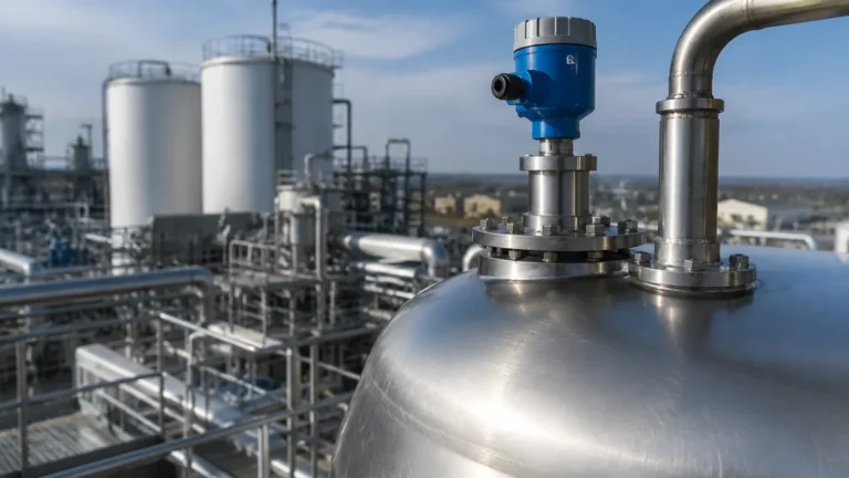
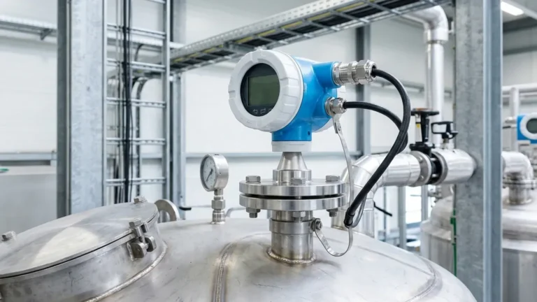
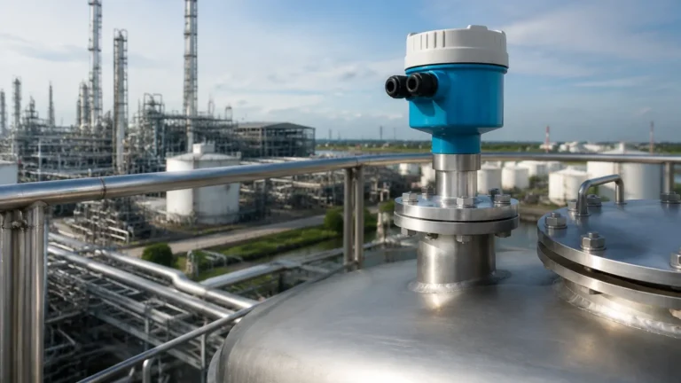
The sensor is typically mounted on a nozzle at the top of the vessel. The nozzle height should be kept as short as possible. If the nozzle is too long or narrow, the radar signal may reflect off the internal edges of the nozzle before even entering the tank, creating a "dead zone" or signal interference at the top of the range.
* Standard Rule: The antenna should extend at least 10mm (0.4 inches) below the bottom of the nozzle to ensure the microwave beam expands freely into the vessel.
2. Radial Placement
The sensor should never be installed in the center of a cylindrical tank. This is a common error that leads to multiple reflections and signal enhancement of noise. Conversely, mounting too close to the wall will cause the beam to hit the side of the tank, leading to energy loss and false echoes.
* Recommended Distance: Install the sensor at a distance of 1/4 to 1/6 of the tank diameter from the side wall. For example, in a 6-meter diameter tank, the sensor should be placed approximately 1 to 1.5 meters from the wall.
3. Avoiding Obstructions
Internal structures such as cooling pipes, ladders, and agitators are the primary causes of measurement failure. When planning the radar level sensor installation, the "keep-out zone" (defined by the beam angle) must be clear of any metallic objects.
* Agitators: If an agitator is present, the sensor should be positioned so the beam is perpendicular to the blades to minimize interference. Advanced signal processing (False Echo Suppression) can often filter out the periodic signal from a moving agitator, but physical clearance is always the preferred engineering solution.
4. Inlet Streams and Turbulence
Never install the radar sensor directly above the filling inlet. The turbulence and the falling product will scatter the radar signal, leading to erratic readings. If the surface is highly turbulent due to mixing, a stilling well or a bypass pipe may be required to provide a calm surface for measurement.
Specialized Installation Scenarios
Stilling Wells and Bypass Pipes
In applications with heavy foam or extremely low dielectric constants (such as liquid nitrogen or certain hydrocarbons), the radar signal may struggle to return a clear echo. Installing the sensor inside a stilling well (a vertical pipe within the tank) or a bypass pipe (mounted externally) constrains the radar waves, significantly increasing the signal strength and eliminating surface turbulence issues.
Solid Materials and Aiming Flanges
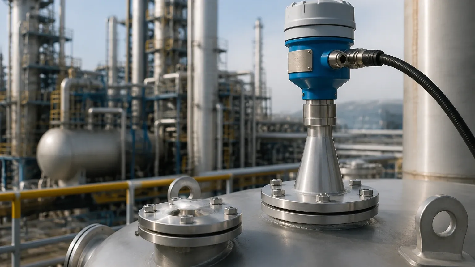
When measuring solids in silos, the material often forms a conical shape (repose angle). In these cases, a fixed vertical installation may not receive a strong return signal. Using an adjustable aiming flange allows the technician to tilt the sensor toward the material's slope, optimizing the echo return for more reliable inventory data.
Limitations and Application Risks
While radar technology is robust, it is not universal. Engineers must be aware of the following limitations:
* Dielectric Constant ($ε_r$): The ability of a medium to reflect radar waves depends on its dielectric constant. Materials with very low $ε_r$ (like dry wood chips or certain oils) may allow the signal to pass through rather than reflect. In these cases, Guided Wave Radar or high-frequency 80GHz units are necessary.
* Heavy Foam: Dense, thick foam can absorb the microwave signal entirely. If the foam is conductive, the radar may reflect off the top of the foam rather than the liquid level.
* Vacuum and Pressure: While radar works well in a vacuum, extreme pressures (above 100 bar) or temperatures (above 450°C) require specialized ceramic seals and cooling extensions to protect the sensor electronics.
Maintenance and Commissioning
Once the radar level sensor installation is complete, commissioning involves "mapping" the tank. This process tells the sensor's software which echoes are static (from internal structures) and which are dynamic (the product level).
1. Empty Tank Mapping: Ideally, perform a signal scan when the tank is empty to identify all internal obstructions.
2. Lens Cleaning: In applications with heavy condensation or crystallization, periodic cleaning of the antenna lens may be required, although many modern 80GHz sensors feature PTFE drop-off lenses that minimize buildup.
Frequently Asked Questions (FAQ)
Q: Can I install a radar sensor on a plastic tank?
A: Yes. Since microwaves can penetrate non-conductive materials, radar sensors can often measure through the top of a plastic tank without a hole, provided the plastic is not too thick and does not contain carbon black.
Q: How does 80GHz technology change installation requirements?
A: 80GHz sensors have a much narrower beam (often as small as 3°). This makes radar level sensor installation much easier because the beam can "miss" obstructions that would have blocked a 26GHz sensor.
Q: What information should I provide a supplier before purchasing?
A: International buyers should confirm the medium name, dielectric constant, operating temperature/pressure, tank height, and a drawing of internal obstructions.
Conclusion
Correct radar level sensor installation is the bridge between high-end instrumentation and actionable industrial data. By understanding the beam geometry, nozzle constraints, and the physical properties of the medium, engineers can ensure that Radar Level Meters provide maintenance-free operation for years. Whether dealing with corrosive chemicals in water treatment or high-temperature liquids in the oil and gas sector, following these factual engineering boundaries ensures a reliable and cost-effective level measurement solution.