Inline Oxygen Sensor
Inline Oxygen Sensor
In the landscape of industrial process control, the inline oxygen sensor stands as a critical analytical tool for real-time monitoring of dissolved oxygen (DO) in liquids or gaseous oxygen in gas streams. Unlike laboratory-based sampling, which can introduce atmospheric contamination or suffer from temperature shifts during transport, inline sensors provide continuous data directly from the process line. This real-time feedback is essential for maintaining product quality, ensuring safety in hazardous environments, and optimizing chemical reactions.
For engineers managing complex fluid systems, oxygen monitoring is often a parallel requirement to level measurement. While instruments such as radar level meters or ultrasonic sensors track the volume and position of the media, the inline oxygen sensor tracks the chemical integrity of the process. This guide explores the fundamental principles, selection criteria, and installation requirements for inline oxygen sensors within industrial automation frameworks.
Understanding Inline Oxygen Measurement Principles
Before selecting a sensor, it is vital to understand the physics governing oxygen measurement. Most industrial inline oxygen sensors operate based on one of two primary principles: electrochemical (amperometric) or optical (fluorescence quenching).
Electrochemical Sensors
Electrochemical sensors, often referred to as Clark cells or polarographic sensors, utilize a cathode and an anode submerged in an electrolyte solution, separated from the process media by a gas-permeable membrane.
1. Diffusion: Oxygen molecules diffuse through the membrane at a rate proportional to the partial pressure of oxygen in the fluid.
2. Reduction: At the cathode, oxygen is chemically reduced, creating an electrical current.
3. Measurement: The resulting current is directly proportional to the oxygen concentration.
These sensors are mature technology but require a constant flow of media across the membrane to prevent "oxygen depletion" at the sensor tip, which would otherwise result in artificially low readings.
Optical Sensors
Optical inline oxygen sensors represent the modern standard for many B2B applications due to their reduced maintenance requirements. They operate on the principle of "fluorescence quenching."
1. Excitation: The sensor emits a specific wavelength of light (usually blue) toward a sensing film containing luminophores.
2. Luminescence: The luminophores become excited and emit light (usually red) as they return to a lower energy state.
3. Quenching: If oxygen molecules are present, they collide with the luminophores and "quench" the luminescence, shortening the decay time and intensity.
4. Phase Shift: The sensor measures the phase shift or decay time of the returned light, which is inversely proportional to the oxygen concentration.
Key Technologies: Optical vs. Electrochemical
Choosing between these technologies depends on the specific demands of the process. The following table summarizes the operational differences:
| Feature | Electrochemical (Amperometric) | Optical (Fluorescence) |
| :— | :— | :— |
| Maintenance | High (Electrolyte/Membrane changes) | Low (Periodic cap replacement) |
| Flow Requirement | Necessary (>10 cm/s or 4 in/s) | None (Works in stagnant media) |
| Calibration Frequency| Frequent | Infrequent |
| Warm-up Time | 15–60 minutes | Immediate |
| Chemical Resistance | Sensitive to H2S and CO2 | Highly resistant |
| Initial Cost | Lower | Higher |
In high-purity water treatment or chemical manufacturing where uptime is critical, optical sensors are frequently preferred because they do not require electrolytes and are not "poisoned" by other gases.
Selection Criteria for Industrial Applications
When specifying an inline oxygen sensor for a project, several technical parameters must be confirmed to ensure compatibility with the existing infrastructure, such as the tanks and piping where Main Page instrumentation like level transmitters are installed.
1. Measurement Range and Sensitivity
Sensors are typically categorized into "High Range" (ppm or mg/L) for general water treatment and "Trace Range" (ppb or µg/L) for power plant boiler feed water or semiconductor manufacturing. Ensure the sensor's detection limit aligns with your process safety margins.
2. Temperature and Pressure Ratings
Industrial processes often operate at elevated pressures. Standard sensors may handle up to 10 bar (145 psi), but high-pressure variants are required for deep-well or pressurized chemical reactors. Temperature compensation is also essential, as oxygen solubility is highly temperature-dependent.
3. Materials of Construction
The sensor body (typically 316L stainless steel) and the O-rings (EPDM, Viton, or Kalrez) must be compatible with the process media. In the food and beverage or pharmaceutical industries, EHEDG or 3-A sanitary certifications are mandatory.
4. Signal Output and Integration
For integration into a PLC or SCADA system, the sensor should offer standard outputs such as 4-20mA (with HART), Modbus RS485, or Profibus. This allows the oxygen data to be logged alongside level and flow data for comprehensive process analysis.
Installation Guidelines and Best Practices
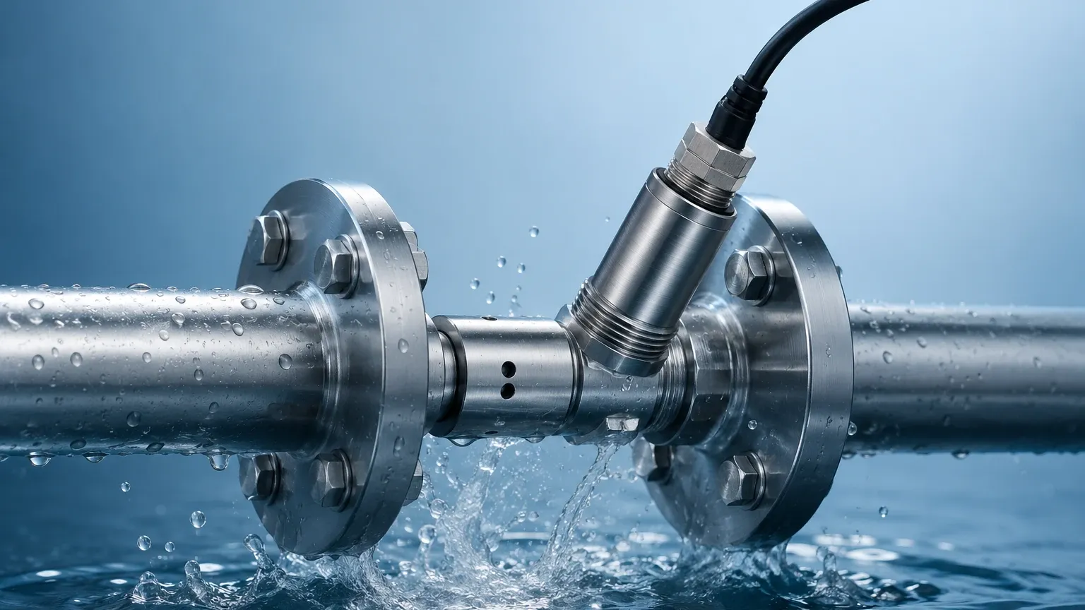
Proper installation is the most significant factor in ensuring the longevity and accuracy of an inline oxygen sensor.
Location and Orientation
* Avoid Air Traps: The sensor should be installed in a vertical pipe section with upward flow or at an angle on a horizontal pipe (typically 15° to 45° from the horizontal) to prevent air bubbles from collecting on the sensing face.
* Bypass Loops: For high-velocity lines or systems requiring frequent maintenance, installing the sensor in a bypass loop with isolation valves allows for calibration without shutting down the main process.
* Submergence: Ensure the sensing element is fully submerged at all times. If the pipe runs partially empty, the sensor will measure the air pocket rather than the liquid.
Flow Considerations
For electrochemical sensors, a minimum flow velocity must be maintained. If the process flow is inconsistent, a flow cell with a regulated bypass may be necessary to provide a stable environment for the membrane.
Integration with Level Meters
In tank environments, the oxygen sensor is often installed at the discharge outlet. By correlating the data from a hydrostatic level transmitter or a radar level meter, operators can determine if oxygen ingress is occurring at specific volume levels, which may indicate a leak in a floating roof or a failing seal.
Maintenance, Calibration, and Troubleshooting
Even the most robust inline oxygen sensor requires a structured maintenance regime.
Calibration Protocols
Calibration should be performed at two points: a "Zero" point (using 99.9% Nitrogen gas) and a "Slope" point (using ambient air or a known standard). Optical sensors hold their calibration significantly longer than electrochemical types, but they should still be verified quarterly.
Handling Fouling and Scaling
In wastewater or heavy industrial applications, bio-fouling or mineral scaling can coat the sensor tip.
* Automated Cleaning: Some housings include spray nozzles for water or chemical cleaning.
* Manual Inspection: Regular visual checks are necessary to ensure the membrane or optical cap is not physically damaged.
Common Risks and Limitations
* Membrane Damage: In electrochemical sensors, solids in the fluid can puncture the membrane, leading to electrolyte leakage and sensor failure.
* Photobleaching: While rare in modern sensors, excessive exposure to direct high-intensity light can degrade the luminophores in optical sensors over several years.
* Pressure Shocks: Rapid pressure changes (water hammer) can damage the sensitive internals of the sensor probe.
Integrating Oxygen Monitoring with Level Control Systems
In many industrial setups, the management of liquids is a multi-parameter task. For instance, in a fermentation tank or a chemical storage vessel, a Welk radar level meter provides the volume data, while the inline oxygen sensor monitors for oxidative degradation.
When these sensors are integrated into a single control loop, the system can trigger automated responses. For example, if oxygen levels rise above a threshold in a nitrogen-blanketed tank, the system can increase nitrogen purge flow while the level meter ensures the tank does not overfill during the process adjustment. This synergy between level measurement and analytical sensing is the cornerstone of modern industrial automation.
Frequently Asked Questions (FAQ)
Q: How often should I replace the sensing element?
A: For optical sensors, the sensing cap typically lasts 1 to 2 years depending on the abrasiveness of the media. For electrochemical sensors, the membrane and electrolyte may need servicing every 3 to 6 months.
Q: Can inline oxygen sensors be used in hazardous areas?
A: Yes, many manufacturers provide ATEX, IECEx, or FM-certified versions for use in explosive atmospheres, common in the oil and gas or chemical sectors.
Q: Does the sensor need to be removed for CIP (Clean-in-Place)?
A: Many industrial inline oxygen sensors are designed to withstand CIP temperatures (up to 130°C / 266°F) and chemicals. However, you must verify that the specific model is rated for "SIP/CIP-capable" before installation.
Q: What is the difference between % saturation and mg/L?
A: % Saturation measures the partial pressure of oxygen relative to the maximum amount that could be dissolved at that temperature and pressure. mg/L (or ppm) measures the actual mass of oxygen in a volume of liquid. Most modern transmitters can toggle between these units.
For engineers seeking to optimize their process monitoring, selecting the right combination of analytical and physical sensors is key. To explore a range of reliable level measurement solutions that complement your analytical instrumentation, visit the Main Page for detailed product specifications and application support.