Interface Radar Level Transmitter
Interface Radar Level Transmitter: A Technical Engineering Guide to Dual-Level Measurement
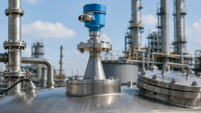
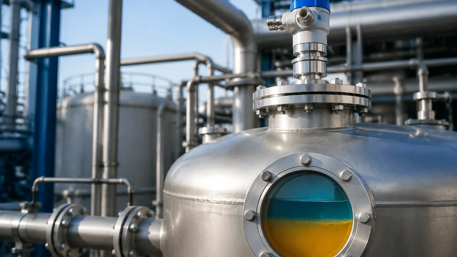
In complex industrial processes, measuring the total level of a liquid is often insufficient. Engineers frequently require the simultaneous measurement of the interface between two immiscible liquids, such as oil and water or solvent and acid. The interface radar level transmitter, primarily utilizing Guided Wave Radar (GWR) technology, has emerged as the industry standard for these challenging applications.
This guide provides a comprehensive technical analysis of how Radar Level Meters function in interface applications, the critical role of dielectric constants, and the practical selection criteria required for reliable industrial automation.
1. Measurement Principles of Interface Radar
To understand the performance of an interface radar level transmitter, one must first understand the physics of Time Domain Reflectometry (TDR). Unlike non-contact radar, which emits electromagnetic pulses through the air, a GWR transmitter guides the pulse along a physical probe (waveguide).
The Physics of Reflection
When a high-frequency microwave pulse travels down the probe, it encounters the first medium (the upper liquid). A portion of the pulse energy is reflected back to the transmitter due to the change in the dielectric constant ($ε_r$) between the gas phase and the liquid phase. This reflection provides the total level measurement.
Because the upper liquid typically has a low dielectric constant (such as hydrocarbons with $ε_r$ between 1.4 and 2.5), a significant portion of the remaining pulse energy continues to travel down the probe through the upper liquid. When this pulse hits the second liquid (the lower layer, typically an aqueous solution with a high dielectric constant, $ε_r > 20$), a second, stronger reflection occurs. This second reflection provides the interface level measurement.
The Role of Dielectric Constants
The success of an interface radar level transmitter depends on two primary conditions:
1. Low Dielectric Upper Layer: The upper liquid must be relatively non-conductive and have a low dielectric constant to allow the microwave pulse to pass through it.
2. Dielectric Differential: There must be a significant difference between the dielectric constants of the two liquids. Generally, a minimum difference of $Δε_r > 10$ is recommended for stable detection, though advanced signal processing can sometimes handle smaller gaps.
2. Technology Comparison: GWR vs. Non-Contact Radar
While non-contact radar is excellent for many applications, it is rarely the first choice for interface measurement. The following table highlights why Guided Wave technology is preferred for interface tasks.
| Feature | Guided Wave Radar (GWR) | Non-Contact Radar |
| :— | :— | :— |
| Interface Capability | Native support; high accuracy for dual levels. | Limited; requires very specific conditions and high power. |
| Signal Loss | Low; signal is contained along the probe. | High; signal scatters at the first liquid surface. |
| Turbulence Impact | Minimal; the probe stabilizes the signal. | Significant; waves can deflect the beam. |
| Foam Sensitivity | Can often penetrate light foam. | Often reflected by foam, causing false readings. |
| Installation | Requires probe immersion into the media. | Top-mounted, no contact with media. |
For most B2B industrial applications involving separators, settling tanks, and distillation columns, the interface radar level transmitter using GWR is the most robust solution.
3. Selection Criteria for Industrial Applications
When specifying a radar level meter for interface detection, international buyers and engineers must evaluate several environmental and chemical factors.
Media Characteristics and the "Rag Layer"
One of the most significant challenges in interface measurement is the emulsion layer, often called the "rag layer." This is a zone where the two liquids have partially mixed. If the emulsion layer is thick (e.g., >50 mm), the radar signal may become diffused, leading to a loss of the interface pulse. In such cases, the transmitter may report the top of the emulsion or the bottom, depending on the configuration and dielectric gradient.
Probe Type Selection
* Coaxial Probes: These offer the highest signal-to-noise ratio. They are ideal for low-dielectric liquids and applications where the probe is installed close to tank walls or internal obstructions. However, they are prone to clogging if the media is viscous or contains solids.
* Twin-Rod Probes: A balance between signal strength and resistance to clogging. Suitable for longer ranges than coaxial probes in some bypass applications.
* Single-Rod Probes: The most common choice for viscous liquids or media that tends to coat the sensor. They require a larger "keep-out zone" from metal obstructions to avoid signal interference.
Process Conditions
Standard industrial interface transmitters are designed to handle pressures from vacuum up to 400 bar and temperatures ranging from -196°C to +450°C. For high-temperature/high-pressure (HTHP) applications, specialized ceramic seals and steam-compensated probes are necessary to maintain accuracy.
4. Installation Considerations and Constraints
Correct installation is paramount for the accuracy of an interface radar level transmitter. Engineers should follow these factual boundaries:
1. Nozzle Geometry: The mounting nozzle should be as short and wide as possible. A long, narrow nozzle can create parasitic reflections that interfere with the detection of the upper liquid level.
2. Bypass Chambers (Magnetic Level Gauge Integration): In many oil and gas applications, GWR probes are installed inside bypass chambers or stilling wells. This protects the probe from turbulence and provides a clean, vertical environment for the measurement. It also allows for maintenance without depressurizing the main vessel.
3. Upper Blocking Distance (Dead Zone): There is a small region at the top of the probe (typically 100 mm to 300 mm) where measurement is not possible. Ensure the maximum liquid level does not enter this zone.
4. Probe Centering: For single-rod probes in stilling wells, centering disks should be used to prevent the probe from touching the pipe wall, which would cause a short circuit of the microwave signal.
5. Practical Selection Table for Engineers
| Application Scenario | Recommended Probe | Key Consideration |
| :— | :— | :— |
| Oil/Water Separator | Coaxial or Twin-Rod | Ensure the oil layer is at least 50-100 mm thick for stable interface detection. |
| Chemical Storage (Corrosive) | PFA/PTFE Coated Single Rod | Material compatibility is the priority; coating prevents corrosion. |
| High-Pressure Boiler | HTHP Coaxial | Needs steam compensation to account for dielectric changes in the gas phase. |
| Wastewater Sump | Single Rod | High resistance to debris and fouling. |
| Small Diameter Tank | Coaxial | Eliminates interference from tank walls and internal structures. |
6. Limitations and Risks
While highly versatile, the interface radar level transmitter is not a universal solution. Engineers must be aware of the following limitations:
* Inverted Dielectrics: If the upper liquid has a higher dielectric constant than the lower liquid (e.g., water over a fluorinated solvent), the GWR cannot measure the interface because the pulse will not penetrate the first layer.
* Conductive Upper Layers: If the top liquid is conductive (like water), the radar signal is completely reflected at the first surface, making interface measurement impossible.
* Coating and Build-up: While GWR is better than many technologies at handling build-up, excessive conductive coating on the probe can attenuate the signal and cause measurement errors.
7. Frequently Asked Questions (FAQs)
Q: Can an interface radar level transmitter measure three layers (e.g., gas, oil, and water)?
A: Yes. The transmitter provides the "Total Level" (gas/oil interface) and the "Interface Level" (oil/water interface) simultaneously via a single probe.
Q: What is the minimum thickness required for the upper liquid layer?
A: Generally, the upper layer must be at least 50 mm to 100 mm thick. If the layer is thinner, the reflections from the top surface and the interface may overlap, making them indistinguishable to the electronics.
Q: Does the density of the liquid affect the radar measurement?
A: No. Unlike hydrostatic pressure transmitters or buoyancy-based displacers, radar technology is independent of liquid density. It relies solely on the dielectric properties and the speed of light.
Q: How do I calibrate the transmitter for a specific liquid pair?
A: Most modern transmitters, such as those provided by Welk, are configured by entering the dielectric constants of the media. Many units also feature a "learning" function where the transmitter maps the tank's internal reflections to ignore static obstacles.
8. Conclusion for International Procurement
For B2B buyers and project engineers, selecting an interface radar level transmitter requires a detailed understanding of the process media's dielectric properties and the physical constraints of the vessel. By utilizing Guided Wave Radar technology, plants can achieve high-precision, maintenance-free measurement of dual-liquid levels, even in high-pressure or turbulent environments.
When requesting a quote or technical specification, ensure you provide the manufacturer with the dielectric constants of both liquids, the operating temperature/pressure range, and the preferred flange standard (e.g., ANSI, DIN, or JIS). For reliable industrial instrumentation and customized OEM/ODM level measurement solutions, professional manufacturers like Welk offer a range of Radar Level Meters designed to meet the rigorous demands of water treatment, chemical processing, and oil and gas automation.