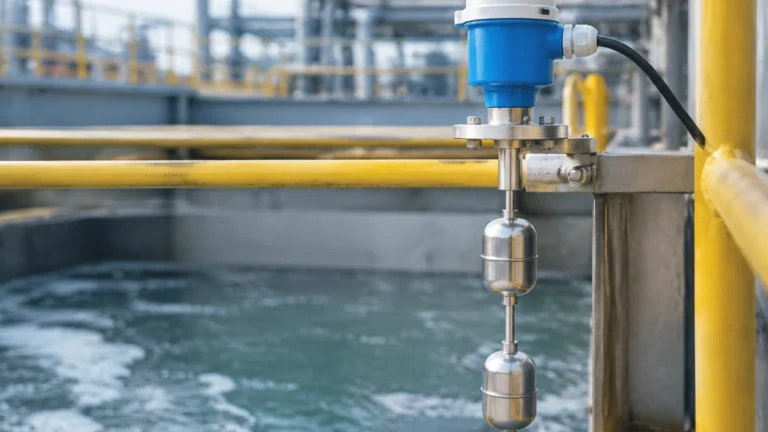
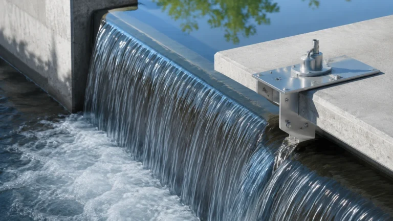
Pressure Instrumentation
Pressure Instrumentation
In the landscape of industrial automation and process control, pressure instrumentation serves as a foundational technology for monitoring, managing, and optimizing liquid and gas systems. While pressure measurement is a distinct field, its application in level sensing—specifically through hydrostatic and differential pressure methods—remains one of the most reliable and widely adopted techniques in water treatment, chemical processing, and the oil and gas sector. For engineers and procurement specialists, understanding the nuances of these instruments is critical to ensuring plant safety, accuracy, and long-term operational efficiency.
Fundamental Principles of Pressure-Based Level Measurement
Before selecting specific hardware, it is essential to understand the physical principles that allow pressure instrumentation to determine the level of a liquid within a vessel. The most common method is hydrostatic level measurement.
The Hydrostatic Principle
Hydrostatic pressure is the pressure exerted by a fluid at equilibrium at a given point within the fluid, due to the force of gravity. The relationship is defined by the formula:
P = ρ · g · h
Where:
* P is the hydrostatic pressure (typically measured in bar or Pascals).
* ρ (Rho) is the density of the liquid (kg/m³).
* g is the acceleration due to gravity (approximately 9.81 m/s²).
* h is the height of the liquid column (meters).
In practical terms, if the density of the liquid remains constant, the pressure measured at the bottom of a tank is directly proportional to the height of the liquid. This allows a pressure transmitter to output a signal (such as 4-20mA) that corresponds linearly to the tank's level.
Gauge vs. Absolute vs. Differential Pressure
Choosing the right type of pressure instrumentation depends heavily on the atmospheric conditions of the vessel:
1. Gauge Pressure: Measures pressure relative to the local atmospheric pressure. This is the standard for vented (open) tanks where the surface of the liquid is exposed to the air.
2. Absolute Pressure: Measures pressure relative to a perfect vacuum. This is less common in level measurement but used in specific high-vacuum industrial processes.
3. Differential Pressure (DP): Measures the difference between two pressure points. In closed or pressurized tanks, the total pressure at the bottom includes both the liquid's hydrostatic pressure and the gas pressure in the headspace. A DP transmitter subtracts the headspace pressure from the total pressure to isolate the liquid level.
Types of Pressure Instrumentation in Level Monitoring
Industrial applications require different form factors depending on the installation environment and the nature of the media being measured.
Submersible Pressure Transmitters
These are specialized sensors designed to be lowered directly into the liquid. They are commonly used in deep wells, reservoirs, and wastewater lift stations. The sensor is housed in a waterproof casing, and the cable includes a vent tube to allow the internal diaphragm to reference atmospheric pressure, ensuring accurate gauge pressure readings.
Externally Mounted Transmitters
For tanks with bottom or side-wall ports, externally mounted transmitters are preferred. These are bolted or screwed into the process connection. They are easier to maintain than submersible units because the sensor can be isolated and removed without emptying the tank, provided a block valve is installed.
Differential Pressure (DP) Transmitters
DP transmitters are the gold standard for pressurized vessels. They utilize two process connections: a high-pressure side at the bottom of the tank and a low-pressure side at the top (in the vapor space). These units are often paired with remote seals and capillaries if the process media is highly corrosive, viscous, or prone to crystallization, preventing the media from entering the transmitter body.
Evaluation Criteria for Industrial Pressure Sensors
Selecting the appropriate pressure instrumentation requires a deep dive into the technical specifications of the application. Failure to account for these variables can lead to premature sensor failure or significant measurement drift.
1. Material Compatibility
The wetted parts of the sensor—primarily the diaphragm and the process connection—must be chemically compatible with the liquid. While 316L stainless steel is the standard, aggressive chemicals may require:
* Hastelloy C: For high resistance to pitting and chloride-induced stress corrosion.
* Tantalum: For extremely corrosive acids.
* Ceramic Diaphragms: Highly resistant to abrasion and chemical attack, though more brittle than metal.
2. Accuracy and Stability
Accuracy is usually expressed as a percentage of the calibrated span (e.g., ±0.1% or ±0.25%). However, long-term stability is equally important. High-quality pressure instrumentation should maintain its calibration over several years to reduce maintenance overhead.
3. Temperature Range and Compensation
Temperature fluctuations affect both the density of the liquid and the physical properties of the sensor's diaphragm. Advanced transmitters include internal temperature compensation to adjust the output signal in real-time, ensuring accuracy across a wide operating range (e.g., -40°C to +85°C).
4. Output Signals and Protocols
In the era of Industry 4.0, the choice of communication protocol is vital. While the 4-20mA analog signal remains the industry standard, digital protocols like HART, RS485 Modbus, and Profibus allow for remote configuration and diagnostic feedback. For a comprehensive overview of how these technologies integrate into broader control systems, you can visit the Main Page to review product options and application support.
Selection Table for Pressure Instrumentation
The following table provides a quick reference for matching pressure technologies with common industrial scenarios.
| Application | Recommended Technology | Key Benefit | Potential Limitation |
| :— | :— | :— | :— |
| Open Water Reservoir | Submersible Hydrostatic | Easy installation; no tank modification. | Vulnerable to lightning/surges in outdoor use. |
| Pressurized Chemical Tank | Differential Pressure (DP) | Compensates for headspace pressure. | Complex installation with impulse lines. |
| Corrosive Acid Storage | External with Tantalum Diaphragm | High chemical resistance. | Higher initial cost. |
| Deep Groundwater Well | High-Accuracy Submersible | Small diameter for narrow boreholes. | Cable stretching over long distances. |
| Hygienic Food/Beverage | Flush Diaphragm Transmitter | No crevices for bacteria growth. | Sensitive to mechanical damage during cleaning. |
Installation and Maintenance Guidelines
Proper installation is the single most important factor in the longevity of pressure instrumentation. Even the most expensive sensor will provide poor data if installed incorrectly.
Mounting Considerations
* Avoid Turbulence: In tanks with agitators or high-velocity inlets, sensors should be installed in a stilling well or away from the direct flow to prevent pressure spikes and mechanical wear.
* Venting: For gauge pressure sensors, ensure the vent tube (in submersible cables) or the vent port (on external units) is clear of obstructions and protected from moisture ingress. Use desiccant filters if operating in high-humidity environments.
* Zero Calibration: Always perform a zero-point calibration after installation. The physical orientation of the sensor and the weight of the liquid in impulse lines can create a small offset that must be accounted for in the control system.
Maintenance Best Practices
* Periodic Inspection: Check for buildup or scaling on the diaphragm. For submersible sensors in wastewater, cleaning the sensor head every 6–12 months is recommended.
* Impulse Line Bleeding: For DP transmitters using impulse lines, ensure there are no trapped gas bubbles in liquid lines (or liquid droplets in gas lines), as these will cause significant measurement errors.
Common Risks and Technical Limitations
While pressure instrumentation is versatile, it is not a "one-size-fits-all" solution. Engineers must be aware of the following risks:
1. Density Changes: Since hydrostatic measurement relies on the assumption of constant density, any change in the liquid's composition or temperature will change the pressure reading, even if the actual level remains the same. If density varies significantly, a radar level meter might be a better choice.
2. Overpressure Events: Sudden surges (water hammer) can deform the sensor diaphragm. Always select a sensor with an overpressure rating at least 2x the maximum working pressure.
3. Vacuum Conditions: Standard hydrostatic sensors may not be designed to handle full vacuum. In vacuum-distillation columns, specialized DP transmitters with vacuum-rated remote seals are required.
Frequently Asked Questions (FAQ)
Q: Can I use a pressure transmitter for solids or powders?
A: Generally, no. Hydrostatic pressure measurement relies on the fluid properties of liquids. Solids do not exert pressure uniformly in all directions and can form "bridges," making pressure-based level measurement inaccurate. For solids, ultrasonic or radar sensors are preferred.
Q: How do I handle a liquid that crystallizes in the process connection?
A: Use a flush diaphragm transmitter or a remote seal system. These designs eliminate the "dead space" or small orifices where liquid can pool and solidify, ensuring the diaphragm remains in contact with the process media.
Q: What is the difference between a 2-wire and a 4-wire transmitter?
A: A 2-wire transmitter uses the same two wires for both power and the 4-20mA output signal, which is highly efficient for wiring. A 4-wire transmitter has separate pairs for power and signal, often used when the device requires more power (e.g., for heated displays or complex local processing).
Q: How does atmospheric pressure affect my reading?
A: If you are using a gauge pressure sensor, the back of the diaphragm is vented to the atmosphere, so changes in barometric pressure are automatically canceled out. If you use an absolute pressure sensor in an open tank, your level reading will drift as the weather changes.
Q: What is the maximum depth a submersible sensor can measure?
A: This is limited by the sensor's range and the strength of the cable. Standard industrial units can often measure up to 200 meters (approx. 650 feet) or more, provided the cable is reinforced with a strain-relief wire (Kevlar or steel).
Conclusion and Next Steps
Pressure instrumentation remains a cornerstone of industrial level measurement due to its simplicity and cost-effectiveness. However, the transition from a basic measurement to a high-performance system requires careful consideration of diaphragm materials, tank dynamics, and density stability. Before moving forward with a project, technical teams should confirm the chemical compatibility of all wetted parts and determine if the vessel's internal pressure necessitates a differential pressure approach.
For those seeking to compare these technologies with other methods such as radar or ultrasonic sensing, further technical documentation and product specifications are available. To explore the full range of industrial measurement solutions, including detailed datasheets and engineering support, please refer to the Main Page for additional guidance.