Wave Sampler
Wave Sampler
In the field of industrial level measurement, the term "wave sampler" refers to the critical electronic subsystem responsible for capturing and digitizing reflected signals in non-contact and contact wave-based sensors. Whether utilizing electromagnetic waves in radar systems or mechanical waves in ultrasonic transmitters, the wave sampler acts as the bridge between the physical environment and the digital processor. For engineers and plant managers, understanding how a wave sampler functions is essential for optimizing accuracy in challenging environments such as chemical reactors, water treatment facilities, and oil storage tanks.
This article explores the technical principles of wave sampling, its application in various level measurement technologies, and the practical considerations required for selecting and installing these systems in industrial settings.
Measurement Principles of Wave Sampling
To understand the wave sampler, one must first understand the time-of-flight (ToF) principle. Most modern level instruments, such as those found on the Main Page of industrial catalogs, rely on sending a signal toward a target and measuring the time it takes for the echo to return.
Pulse Sampling and Time Expansion
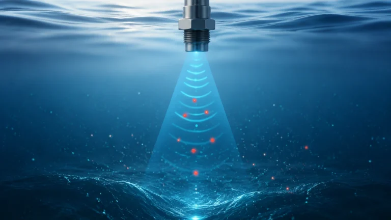
In pulse radar and ultrasonic systems, a short burst of energy is emitted. Because electromagnetic waves travel at the speed of light (approximately 300,000 km/s), the return time for a short distance—say, 10 meters—is incredibly brief (about 67 nanoseconds). Standard microprocessors cannot sample data at the gigahertz rates required to resolve these times directly.
The wave sampler solves this through a technique known as Equivalent Time Sampling (ETS). Instead of capturing the entire return signal in a single pass, the sampler takes a single data point from successive pulses, slightly shifting the sampling gate each time. Over thousands of pulses, the system reconstructs a "time-expanded" version of the wave. This allows the electronics to analyze a signal that appears to move in milliseconds rather than nanoseconds, enabling high-precision distance calculation.
Frequency Modulated Continuous Wave (FMCW) Sampling
In FMCW radar, the wave sampler operates differently. Instead of measuring time directly, the instrument emits a continuous signal with a constantly changing frequency (a sweep). When the reflected signal returns, it is mixed with the currently emitted signal. The difference in frequency (the beat frequency) is proportional to the distance. Here, the wave sampler captures the interference pattern, which is then processed using a Fast Fourier Transform (FFT) to determine the level.
The Role of the Wave Sampler in Signal Integrity
The primary function of the wave sampler is to produce a clean "echo curve" or "envelope curve." This curve represents the amplitude of reflected energy over distance. A high-quality wave sampler must distinguish between the true material level and various forms of interference, such as:
1. Internal Reflections: Signals bouncing off the sensor nozzle or mounting flange.
2. Obstructions: Reflections from agitators, ladders, or heating coils inside the tank.
3. Multiple Echoes: Signals that bounce between the liquid surface and the tank roof before returning to the sensor.
By employing advanced sampling algorithms, the instrument can apply "False Echo Suppression," effectively "learning" the static environment of the tank and ignoring reflections that do not correspond to the moving material level.
Selection Criteria for Level Measurement Technologies
Choosing the right instrument depends heavily on how the wave sampler interacts with the specific properties of the medium and the vessel. Below is a comparison table for common technologies utilizing wave sampling.
Technology Comparison Table
| Technology | Wave Type | Sampling Method | Ideal Application | Limitations |
| :— | :— | :— | :— | :— |
| 80GHz Radar | Electromagnetic | FMCW / High-Res Sampling | Narrow tanks, agitated liquids | Extremely high-density foam |
| Guided Wave Radar | Electromagnetic | Pulse / ETS | Low dielectric liquids, bypass pipes | Physical contact required |
| Ultrasonic | Acoustic | Pulse / ToF | Water treatment, open channels | Affected by wind, vacuum, and vapor |
| 6GHz/26GHz Radar | Electromagnetic | Pulse / ETS | Large storage tanks, heavy dust | Larger beam angle, nozzle sensitive |
Practical Selection Considerations
When evaluating a system with a specific wave sampler configuration, engineers should confirm several factors before procurement:
Dielectric Constant (εr)
For radar-based wave samplers, the dielectric constant of the medium is the most critical factor. Materials with high εr (like water, εr ≈ 80) reflect waves strongly, making them easy to sample. Materials with low εr (like hydrocarbons or plastic pellets, εr < 2) allow waves to pass through, resulting in a weak return signal. In these cases, a wave sampler with high sensitivity or a Guided Wave Radar (GWR) system is necessary.
Turbulence and Surface Conditions
If the surface is turbulent or covered in foam, the wave sampler may receive a "fuzzy" or scattered signal. High-frequency FMCW radars (80GHz) are often preferred here because their narrow beam and advanced sampling logic can better filter out surface noise compared to lower-frequency options.
Update Time vs. Accuracy
In dynamic processes where levels change rapidly (e.g., small buffer tanks), the sampling rate must be high. While ETS provides high resolution, it requires multiple pulses to build a curve. Modern high-speed wave samplers can now provide update rates of less than one second without sacrificing millimeter-level precision.
Installation and Engineering Guidelines
Even the most advanced wave sampler will fail if the physical installation is flawed. Follow these guidelines to ensure optimal signal acquisition:
1. Nozzle Geometry: The nozzle should be as short as possible. If the nozzle is too long or narrow, the wave sampler will capture "ringing" or reflections from the nozzle walls, which can mask the true level near the top of the tank.
2. Beam Path Clearance: Ensure the signal beam (typically a cone of 3° to 10°) does not intersect with inflow streams, agitator blades, or structural supports. Use the instrument’s software to map out these obstructions during commissioning.
3. Mounting Orientation: For radar, the sensor should be mounted such that the wave travels perpendicular to the liquid surface. For solids, an aiming flange may be required to compensate for the angle of repose of the material.
4. Environmental Protection: In outdoor installations, ensure the sensor housing is rated for the environment (e.g., IP66/67). Rapid temperature changes can cause condensation on the antenna, which attenuates the signal before it reaches the wave sampler.
Limitations and Challenges
Despite advancements in digital sampling, certain physical limitations remain:
* The Dead Zone (Blocking Distance): Every wave-based sensor has a minimum distance near the antenna where it cannot accurately sample the return wave. This is due to the time required for the electronics to switch from "transmit" to "receive" mode.
* Vapor and Gas Layers: While radar waves pass through most gases, heavy vapors (like high-pressure steam) can slow down the wave, leading to a measurement error. In these specialized cases, compensation sensors or specific sampling calibrations are required.
* Signal Attenuation: In very tall silos (over 30 meters) containing dusty solids, the signal can be absorbed or scattered. A wave sampler with a high dynamic range is required to pull the signal out of the noise floor.
Frequently Asked Questions (FAQs)
Q: Can a wave sampler work in a vacuum?
A: Radar-based samplers work perfectly in a vacuum because electromagnetic waves do not require a medium. However, ultrasonic samplers will not work, as sound waves require air or gas to travel.
Q: How does foam affect the wave sampling process?
A: It depends on the foam type. Dry, airy foam may be transparent to radar, allowing the sampler to see the liquid below. Thick, wet foam may reflect the signal, causing the sampler to report the top of the foam as the level. In some cases, foam can completely absorb the signal, leading to a "loss of echo."
Q: Is it possible to update the sampling software in the field?
A: Most modern industrial transmitters allow for firmware updates. This can improve the wave sampler's ability to handle new types of interference or process noise as the plant's operational conditions change.
Q: What is the difference between a wave sampler and a signal processor?
A: The wave sampler is the hardware/firmware stage that captures the raw data from the sensor's front end. The signal processor is the higher-level logic that interprets that data, applies filters, and converts it into a 4-20mA or digital output (like HART or Modbus).
Conclusion
The wave sampler is the unsung hero of modern level instrumentation. By effectively managing the high-speed transition from physical wave to digital data, it enables the precision and reliability required for automated industrial processes. Whether you are managing a simple water tank or a complex chemical reactor, selecting an instrument with a robust sampling architecture is the first step toward operational excellence.
For more information on specific instrument models and technical specifications, please visit the Main Page to explore our full range of radar, ultrasonic, and hydrostatic measurement solutions.