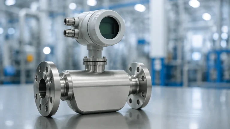
High Pressure Flow Meter
High Pressure Flow Meter
In industrial process control, the measurement of fluid movement under extreme conditions is a critical requirement for safety, efficiency, and fiscal accuracy. A high pressure flow meter is a specialized instrument designed to operate in environments where internal pressures significantly exceed standard atmospheric or low-pressure process conditions—often ranging from 100 bar (1,450 psi) to over 1,000 bar (14,500 psi). These instruments are foundational in sectors such as oil and gas extraction, chemical synthesis, hydraulic power systems, and high-pressure water treatment.
Selecting the appropriate technology for high-pressure applications requires a deep understanding of fluid dynamics, material science, and mechanical integrity. Unlike standard flow meters, high-pressure variants must account for the physical stress on the sensor body, the potential for fluid density changes, and the stringent safety protocols required to prevent catastrophic containment failure.
Measurement Principles for High-Pressure Applications
Before selecting a specific meter, it is essential to understand the physics governing different measurement technologies. Each principle reacts differently to the mechanical constraints of high-pressure housings.
Differential Pressure (DP) Measurement
Differential pressure remains one of the most common methods for high-pressure flow measurement. Based on Bernoulli’s principle, a restriction (such as an orifice plate, Venturi tube, or flow nozzle) is placed in the flow stream. This creates a pressure drop proportional to the square of the flow rate.
In high-pressure scenarios, the primary challenge is not the pressure drop itself, but the static pressure acting on the transmitter. High-pressure DP systems utilize robust manifolds and reinforced diaphragms to ensure that the small differential signal can be accurately extracted from a high-base static pressure. These systems are favored for their lack of moving parts and their ability to be serviced without breaking the main process line if redundant manifolds are used.
Coriolis Mass Flow Measurement
Coriolis meters measure mass flow directly by inducing a vibration in the flow tubes. As fluid passes through the vibrating tubes, the Coriolis force causes a phase shift between the inlet and outlet sides, which is directly proportional to the mass flow rate.
For high-pressure service, Coriolis meters require thick-walled sensing tubes. While this increases the mechanical strength, it can also reduce the sensitivity of the meter. Engineers must balance the need for pressure containment with the signal-to-noise ratio. Coriolis meters are highly valued in high-pressure chemical injection because they are independent of fluid density and viscosity changes.
Turbine Flow Measurement
Turbine meters utilize a rotor suspended in the fluid stream. The velocity of the fluid causes the rotor to spin at a rate proportional to the flow volume. A pickup coil outside the pressure boundary detects the passage of the rotor blades.
In high-pressure applications, the housing is typically machined from solid stainless steel or high-strength alloys. The primary engineering concern is the bearing life. High static pressures can influence the lubrication properties of the fluid, and the mechanical stress on the rotor shaft must be carefully managed to prevent premature wear.
Ultrasonic (Transit-Time) Measurement
Ultrasonic meters measure the time difference between acoustic pulses traveling with and against the flow. Because the transducers can often be mounted externally (clamp-on) or in high-pressure wetted plugs, they offer a non-intrusive or minimally intrusive solution.
At high pressures, the speed of sound in the fluid may change significantly. Advanced high pressure flow meter electronics must include compensation algorithms for these variations. The density of the fluid at high pressure often improves acoustic coupling, making ultrasonic technology highly effective for high-pressure gas or liquid pipelines.
Technical Selection Criteria
Choosing the right meter involves evaluating the specific constraints of the installation. The following table provides a comparison of common technologies used in high-pressure environments.
Comparison Table: High-Pressure Flow Technologies
| Technology | Typical Max Pressure | Accuracy (Liquid) | Primary Advantage | Main Limitation |
| :— | :— | :— | :— | :— |
| Differential Pressure | 400+ bar | ±0.5% to ±2% | No moving parts; versatile | Permanent pressure loss |
| Coriolis | 1,000+ bar | ±0.1% | Direct mass flow; high accuracy | High initial cost; size limits |
| Turbine | 700+ bar | ±0.25% | Excellent repeatability | Susceptible to debris/wear |
| Ultrasonic | 500+ bar | ±1.0% | Low pressure drop; non-intrusive | Sensitive to flow profile |
| Vortex | 250 bar | ±1.0% | Wide turndown; low maintenance | Minimum Reynolds number req. |
Material and Construction Standards
In high-pressure instrumentation, the "wetted parts" (the materials in contact with the fluid) must meet rigorous metallurgical standards. Common materials include:
* 316L Stainless Steel: The standard for general corrosion resistance and moderate high-pressure applications.
* Duplex and Super Duplex Stainless Steel: Used for high-strength requirements and resistance to chloride-induced stress corrosion cracking.
* Hastelloy C276: Reserved for highly aggressive chemical environments where high pressure and acidity coexist.
Furthermore, the connection types are critical. Standard NPT threads are often avoided in favor of flanged connections (ANSI/ASME B16.5 or B16.47) or specialized high-pressure fittings like Autoclave or Grayloc, which provide a more reliable metal-to-metal seal.
Installation Considerations for High-Pressure Systems
Proper installation is as important as the meter selection itself. Failure to follow engineering best practices can lead to measurement errors or safety hazards.
1. Straight Pipe Runs: Most high pressure flow meter types (except Coriolis) require a specific length of straight pipe upstream and downstream to stabilize the flow profile. For high-pressure gas, these requirements may be more stringent to prevent turbulence-induced noise.
2. Pressure Pulsation Dampening: In systems powered by reciprocating pumps, pressure pulsations can interfere with the meter's sensor. Installing a pulsation dampener or choosing a meter with high-frequency sampling can mitigate this.
3. Seal Integrity: All seals and gaskets must be rated for the maximum allowable working pressure (MAWP) of the system. In high-pressure hydrogen or gas service, fugitive emission standards must be met.
4. Orientation: For liquid applications, the meter should be installed in a position where the pipe remains full. For gas applications, the meter should be oriented to prevent the accumulation of condensates in the sensor body.
Limitations and Operational Risks
While a high pressure flow meter is built for durability, it is not immune to the laws of physics. Users should be aware of the following risks:
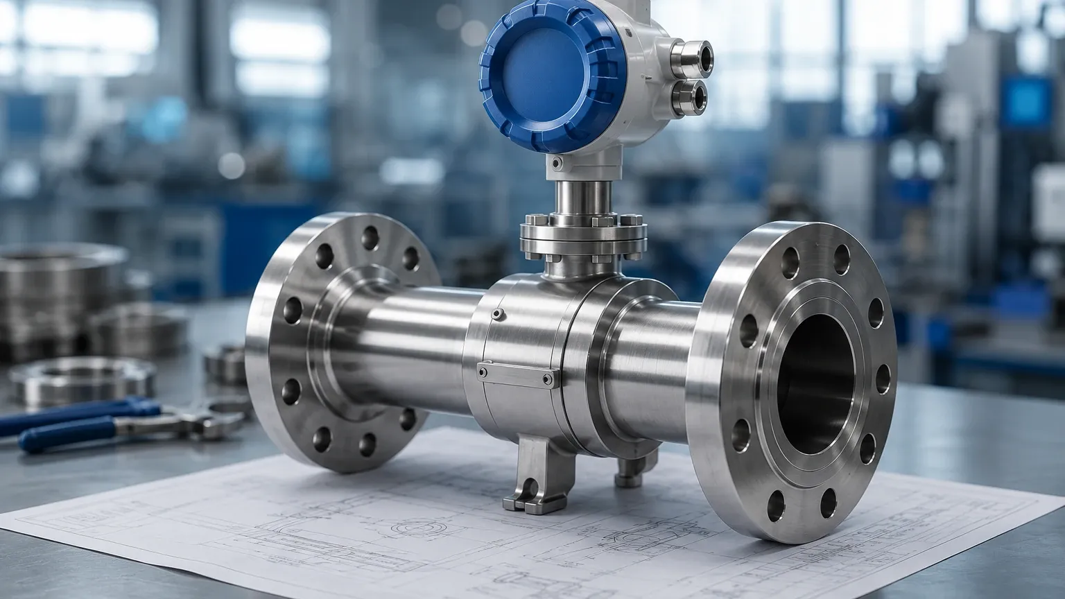
* Material Fatigue: Repeated pressure cycling can lead to micro-fractures in the meter body. Regular non-destructive testing (NDT) is recommended for critical safety applications.
* Calibration Shift: Under extreme pressure, the physical dimensions of the meter (e.g., the diameter of an orifice or the volume of a Coriolis tube) can change slightly. High-end meters include "pressure effect" compensation factors in their software.
* Cavitation: In high-pressure liquid systems, a significant pressure drop across a meter can cause the fluid to vaporize locally, leading to cavitation. This can erode the internal components of turbine or DP meters rapidly.
Integration with Level Measurement Systems
In many industrial processes, flow measurement is used in conjunction with level measurement to provide a complete picture of mass balance. For instance, in a high-pressure separator tank, a high pressure flow meter monitors the output while a radar or ultrasonic level sensor monitors the inventory. For professional-grade level instrumentation that complements high-pressure flow systems, engineers often refer to the Main Page of specialized manufacturers like Welk to ensure compatibility across the entire control loop.
Welk provides a range of industrial level measurement instruments, including radar level meters and ultrasonic level sensors, which are frequently used in the same high-pressure environments as the flow meters discussed here. Ensuring that both flow and level instruments are rated for the same process conditions is vital for system-wide safety.
Frequently Asked Questions (FAQ)
Q: Can a standard flow meter be used in a high-pressure line if the flow rate is low?
No. The pressure rating of a meter is independent of the flow rate. Using a meter above its rated pressure can result in the housing bursting, regardless of how slow the fluid is moving.
Q: How does fluid density change affect high-pressure gas flow measurement?
At high pressures, gases do not behave like ideal gases. The compressibility factor (Z) must be calculated to determine the actual density. If using a volumetric meter (like a turbine or vortex), a separate pressure and temperature transmitter are required to calculate the mass flow.
Q: What is the maintenance cycle for a high pressure flow meter?
This depends on the fluid. For clean fluids, an annual calibration check is standard. For abrasive or corrosive fluids, the meter should be inspected every six months for wall thinning or internal wear.
Q: Are clamp-on ultrasonic meters safe for high pressure?
Yes, clamp-on meters are inherently safe for high pressure because they do not require cutting into the pipe. However, the pipe wall thickness must be precisely measured, as thick-walled high-pressure pipes can attenuate the ultrasonic signal.
Conclusion
The implementation of a high pressure flow meter requires a balance of safety engineering and measurement precision. By understanding the underlying principles—whether it be the mass flow detection of a Coriolis meter or the robust simplicity of a differential pressure system—engineers can select a solution that maintains process integrity. Always ensure that the selected instrument meets the relevant industrial standards (such as PED or ASME) and consider the long-term maintenance requirements of the specific fluid being measured. For comprehensive process control, integrating these flow solutions with reliable level measurement technology ensures optimal performance across the entire industrial application.