Ph Meter Probe
Ph Meter Probe
In industrial process control, the measurement of liquid acidity or alkalinity is as fundamental as monitoring pressure or volume. A ph meter probe serves as the primary sensing element in this analytical chain, converting chemical activity into an electrical signal that can be interpreted by a transmitter or controller. For engineers and plant managers in sectors such as water treatment, chemical processing, and industrial automation, selecting the correct probe is critical for ensuring process stability, equipment longevity, and regulatory compliance.
While industrial facilities often focus on physical parameters like those found on the Main Page of level measurement systems, liquid analysis through pH monitoring provides the chemical context necessary for a complete operational overview. This article explores the technical principles, selection criteria, and maintenance protocols for industrial-grade pH probes.
Measurement Principles of the pH Probe
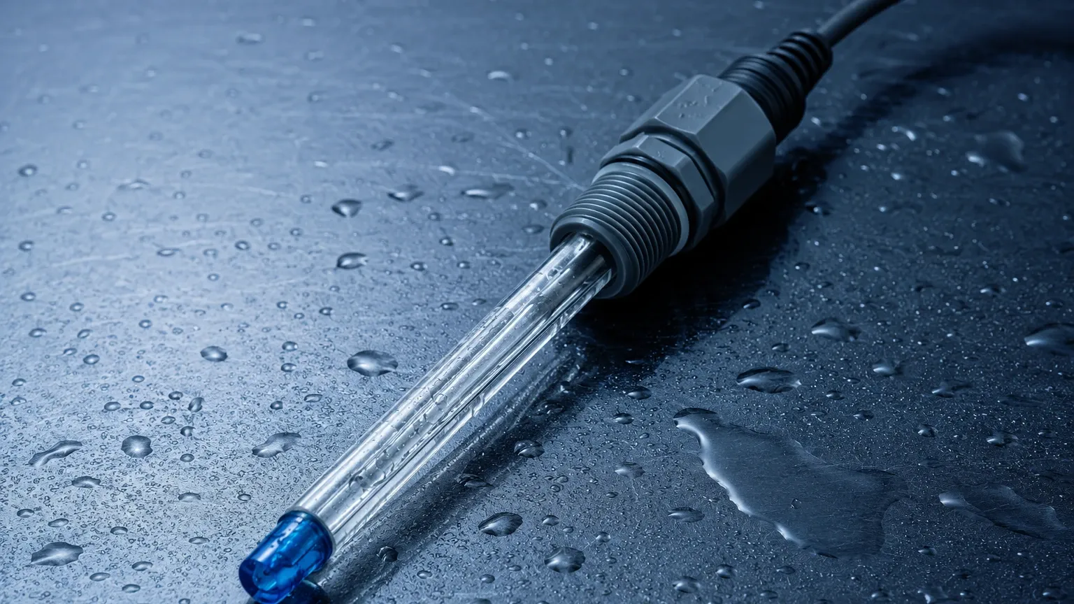
The operation of a ph meter probe is based on the principle of potentiometry. It functions as an electrochemical cell, typically consisting of two primary electrodes: a sensing electrode and a reference electrode. In most modern industrial applications, these are combined into a single body known as a combination electrode.
The Glass Electrode
The sensing component is a thin, hydrogen-ion-sensitive glass membrane. When this membrane is immersed in a liquid, a hydrated gel layer forms on both the inner and outer surfaces. The hydrogen ions ($H^+$) in the process liquid exchange with the ions in the gel layer. This ion exchange creates a potential difference across the glass membrane that is proportional to the hydrogen ion concentration (pH) of the liquid.
The Reference Electrode
To measure the potential generated by the glass membrane, a stable reference point is required. The reference electrode provides a constant electrical potential, regardless of the pH of the solution. This is usually achieved using a silver/silver chloride (Ag/AgCl) system immersed in a concentrated potassium chloride (KCl) electrolyte. The electrical circuit is completed through a junction—a porous material that allows a small amount of electrolyte to interface with the process liquid.
The Nernst Equation
The relationship between the measured voltage (mV) and the pH value is defined by the Nernst Equation. At a standard temperature of 25°C (298.15 K), a change of one pH unit corresponds to a theoretical change of 59.16 mV. Because this relationship is temperature-dependent, industrial probes often incorporate an Automatic Temperature Compensation (ATC) element, such as a Pt100 or Pt1000 thermistor, to adjust the slope of the measurement in real-time.
Key Components and Construction
Understanding the construction of a ph meter probe is essential for identifying the right tool for specific industrial environments.
1. Sensing Membrane: Different glass formulations are used depending on the application. High-temperature glass is designed to resist the accelerated aging caused by heat, while "HF-resistant" glass is used in processes containing hydrofluoric acid, which would otherwise dissolve standard glass.
2. Junction Type: The junction is often the "weakest link" in a pH probe.
* Ceramic Junctions: Common in clean water applications but prone to clogging in oily or high-solid environments.
* Teflon (PTFE) Junctions: Offer better resistance to fouling and chemical attack.
* Open Junctions: Use a solid polymer electrolyte that contacts the process directly, ideal for high-solid slurries or wastewater.
3. Electrolyte: Probes may use liquid, gel, or solid polymer electrolytes. Gel and solid electrolytes are preferred in industrial settings as they are "maintenance-free" and do not require refilling.
4. Housing Material: While the sensing tip is glass, the body can be made of glass, epoxy, or chemically resistant plastics like Ryton (PPS) or PVDF to withstand mechanical stress.
Practical Selection Table for Industrial Applications
Choosing a ph meter probe requires matching the probe's technical specifications to the process conditions. The following table provides a general guideline for selection.
| Application | Recommended Junction | Membrane Type | Body Material |
| :— | :— | :— | :— |
| Municipal Water Treatment | Ceramic | General Purpose | Epoxy / Glass |
| Chemical Processing (Aggressive) | Teflon (PTFE) | High Temperature | PVDF / Ryton |
| Wastewater with Solids | Open / Solid Polymer | Ruggedized Glass | Ryton |
| Pure Water / Low Conductivity | Large Surface Ceramic | Low Resistance | Glass |
| Hydrofluoric Acid Solutions | Teflon (PTFE) | HF-Resistant | PVDF |
| High-Pressure Pipelines | Double Junction / Gel | Heavy Duty | Stainless Steel / PPS |
Installation Considerations
Proper installation is as important as probe selection for ensuring accurate readings and a long service life. In industrial environments, probes are typically installed in one of three ways:
1. In-Line Installation
The probe is mounted directly into a process pipe using a flow-through cell or a threaded adapter. This allows for real-time monitoring of the flowing liquid. It is vital to ensure that the flow rate does not exceed the manufacturer's specifications, as high velocity can cause "streaming potentials" or mechanical damage to the glass bulb.
2. Submersion Installation
In tanks or open channels, the ph meter probe is mounted at the end of a submersion pipe. The cable must be protected from moisture ingress, and the probe should be positioned where there is sufficient agitation to ensure a representative sample, but away from areas where heavy solids might impact the sensor.
3. Retractable Assemblies
For processes that cannot be shut down for maintenance, retractable housings allow the probe to be removed, cleaned, and calibrated while the process remains under pressure. This is standard practice in chemical and oil and gas industries.
Installation Checklist:
* Orientation: Probes should generally be installed at an angle of at least 15° above the horizontal to ensure the internal electrolyte stays in contact with the pH bulb and to prevent air bubbles from being trapped.
* Cable Length: pH signals are high-impedance and sensitive to electrical noise. Use shielded cables and keep lengths as short as possible, or use a pre-amplifier/digital converter at the sensor head.
* Grounding: Ensure the process liquid is properly grounded to prevent stray currents from interfering with the millivolt signal.
Maintenance and Calibration Protocols
A ph meter probe is a consumable item; its sensitivity will degrade over time due to chemical exposure and physical wear. Regular maintenance is required to maintain accuracy.
Calibration
Calibration should be performed using at least two buffer solutions (usually pH 4.0, 7.0, or 10.0) that bracket the expected process range.
1. Zero Point (Offset): Calibrated at pH 7.0. A new probe should ideally read 0 mV at pH 7.0.
2. Slope: Calibrated with a second buffer. The slope indicates the efficiency of the probe. If the slope drops below 85% of the theoretical Nernstian value, the probe should be cleaned or replaced.
Cleaning
Fouling of the membrane or junction is the most common cause of measurement drift.
* General debris: Clean with a mild detergent and soft brush.
* Mineral scale: Soak in 5% Hydrochloric Acid (HCl) for a few minutes.
* Oil and Grease: Use an isopropyl alcohol or specialized solvent.
* Proteins: Use a pepsin/HCl cleaning solution.
Storage
Never store a ph meter probe in distilled or deionized water, as this will leach ions out of the reference electrolyte and the glass membrane. Probes should be stored in a specialized storage solution (usually 3M or 4M KCl) or a pH 4.0 buffer to keep the membrane hydrated.
Common Risks and Limitations
Despite their versatility, pH probes have inherent limitations that engineers must account for:
* Dehydration: If the probe dries out, the hydrated gel layer on the glass membrane collapses. While some probes can be rejuvenated by soaking in KCl, prolonged dehydration often leads to permanent failure.
* Sodium Error: In highly alkaline solutions (pH > 12), the probe may respond to sodium ions ($Na^+$) as if they were hydrogen ions, leading to a falsely low pH reading. Specialized "low sodium error" glass is required for these applications.
* Pressure Limitations: Standard probes are often rated for pressures up to 6 or 7 bar (approx. 90-100 psi). In high-pressure applications, specialized pressure-compensated probes or housing systems are necessary to prevent the process liquid from forcing its way into the reference junction.
* Lifespan: In clean water, a probe may last 2 years. In aggressive chemical processes at high temperatures, the lifespan may be reduced to a few weeks or months. This should be factored into the operational budget.
Frequently Asked Questions (FAQ)
Q: How often should I calibrate my industrial pH probe?
A: This depends entirely on the process. In stable water treatment applications, once a month may suffice. In aggressive chemical reactions, daily or even shift-wise calibration may be necessary. Monitoring the "slope" and "offset" during calibration will help determine the optimal frequency.
Q: Can I use a lab pH probe in an industrial process?
A: It is not recommended. Lab probes are typically made of thin glass and lack the mechanical strength, pressure ratings, and fouling-resistant junctions required for industrial environments. They will likely fail prematurely.
Q: Why is my pH reading drifting even after calibration?
A: Drift is often caused by a clogged reference junction or electrical interference (ground loops). Check for coating on the sensor tip and ensure the cable shielding is correctly terminated.
Q: What is the difference between a PT100 and a PT1000 in a pH probe?
A: Both are resistance temperature detectors (RTDs). The PT1000 has a higher resistance and is generally less affected by the resistance of the lead wires, making it slightly more accurate for long cable runs without a transmitter nearby.
Conclusion
The ph meter probe is a sophisticated electrochemical sensor that requires careful selection and diligent maintenance to provide reliable data. By understanding the relationship between the glass membrane, the reference junction, and the specific chemistry of the process, industrial operators can significantly improve the accuracy of their liquid analysis. For comprehensive solutions in industrial automation and measurement, including advanced level and flow instrumentation, engineers are encouraged to review the technical resources and product options available on the Main Page of specialized manufacturers like Welk.