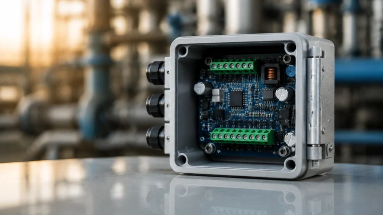
Mechanical Temperature Switch
Mechanical Temperature Switch
In the landscape of industrial process control, the mechanical temperature switch remains a fundamental component for safety and automation. Unlike electronic sensors that require continuous power and complex signal processing, a mechanical temperature switch operates on physical principles of thermal expansion to open or close electrical circuits at predefined temperature thresholds. For engineers and facility managers, understanding the mechanics, selection criteria, and integration of these devices is essential for maintaining operational integrity, especially when paired with other instrumentation like level meters and pressure transmitters.
Industrial environments, ranging from chemical processing plants to water treatment facilities, rely on these switches as reliable "watchdogs." They serve as the primary line of defense against overheating or freezing, often acting as redundant safety backups to more sophisticated digital systems. This guide explores the technical foundations of mechanical temperature switches and provides a practical framework for their application in modern industry.
Measurement Principles of Mechanical Temperature Switches
To select the right instrument, one must first understand how a mechanical temperature switch converts a change in thermal energy into mechanical work. There are two primary technologies used in industrial mechanical switches: bimetallic elements and fluid-filled capillary systems.
Bimetallic Strip Mechanism
The bimetallic switch utilizes the principle of differential thermal expansion. It consists of two different metal strips (such as brass and steel) bonded together. Because these metals expand at different rates when heated, the strip is forced to bend toward the side with the lower expansion coefficient. This physical displacement is calibrated to trigger a microswitch at a specific temperature. Bimetallic switches are typically compact and cost-effective, making them ideal for direct-mounting applications where the sensing element is in close proximity to the switch housing.
Bulb and Capillary (Fluid-Filled) Systems
This system relies on the expansion of a liquid, gas, or vapor trapped within a sensing bulb, connected to a bellows or Bourdon tube via a narrow capillary tube. As the temperature at the bulb increases, the internal pressure rises, causing the bellows to expand. This expansion exerts force on a mechanical linkage that trips the electrical contact.
One of the primary advantages of the bulb and capillary design is the ability for remote mounting. The sensing bulb can be placed inside a high-temperature reactor or a deep tank, while the switch housing remains in a more accessible or cooler environment, connected by several meters of capillary tubing.
Key Components and Construction
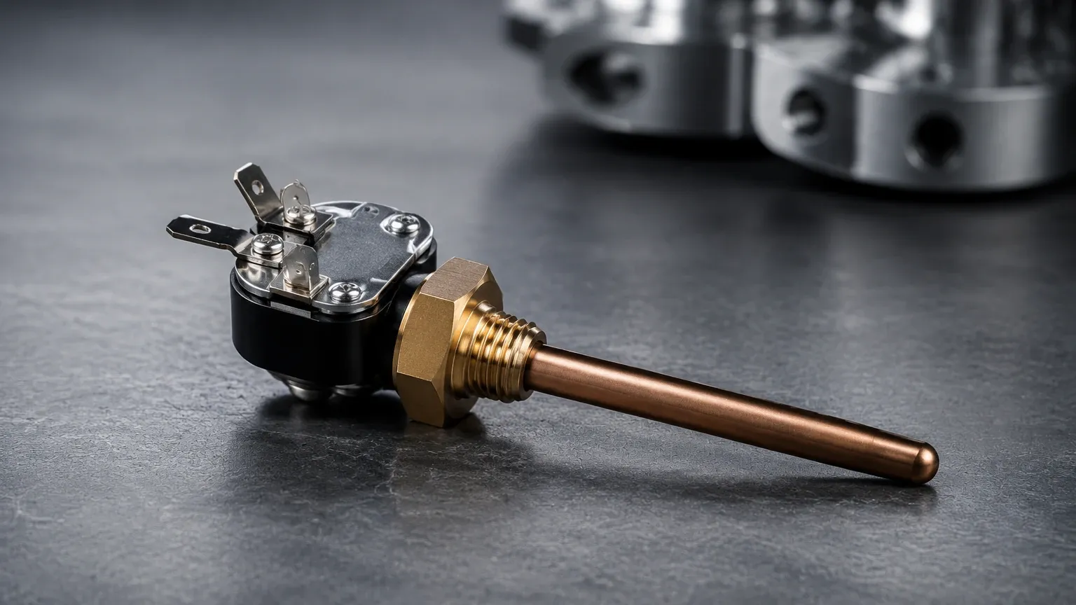
A high-quality mechanical temperature switch is composed of several critical sub-assemblies designed to withstand harsh industrial conditions:
1. The Sensing Element: This is the part in direct thermal contact with the process. In bimetallic types, it is the strip itself; in capillary types, it is the bulb (often made of stainless steel or copper).
2. The Adjustment Mechanism: Most industrial switches allow the user to set the trip point. This is usually a calibrated spring and screw assembly that opposes the force generated by the sensing element.
3. The Microswitch: This is the electrical component that performs the switching action. "Snap-action" microswitches are preferred because they prevent "arcing" by ensuring a fast, decisive contact transition regardless of how slowly the temperature changes.
4. The Housing: To protect the internal mechanics from dust, moisture, and corrosive vapors, the housing is typically rated to IP65, IP66, or even IP68. For hazardous areas, explosion-proof (Ex d) or intrinsically safe (Ex i) housings are mandatory.
Selection Criteria for Industrial Applications
Choosing a mechanical temperature switch requires a detailed analysis of the process requirements. Failure to account for variables like deadband or media compatibility can lead to premature failure or inaccurate switching.
Temperature Range and Setpoint
The operating range should be selected so that the desired setpoint falls within the middle 30% to 60% of the instrument's total range. This ensures the best accuracy and longevity of the mechanical components. For example, if a process needs to trigger an alarm at 80°C (176°F), a switch with a range of 20°C to 120°C is more appropriate than one that tops out at 85°C.
Deadband (Hysteresis)
The deadband is the difference between the temperature at which the switch activates and the temperature at which it resets. In mechanical switches, a certain amount of deadband is inherent due to friction and the physics of the snap-action mechanism. If a switch closes at 100°C and has a 5°C deadband, it will not open again until the temperature drops to 95°C. Engineers must ensure the deadband is narrow enough for process control but wide enough to prevent "chattering" (rapid cycling) near the setpoint.
Environmental and Media Compatibility
The sensing bulb or bimetal sheath must be compatible with the process fluid. 316 Stainless Steel is the standard for most applications, but highly corrosive chemical processes may require Hastelloy or PTFE coatings. Additionally, the ambient temperature at the switch housing must be considered, as extreme heat or cold can affect the calibration of the internal spring mechanisms.
Comparison Table: Bimetallic vs. Capillary Switches
| Feature | Bimetallic Switch | Bulb and Capillary Switch |
| :— | :— | :— |
| Sensing Method | Solid metal expansion | Fluid/Gas pressure expansion |
| Typical Range | -70°C to +500°C | -40°C to +350°C |
| Accuracy | ±2% to ±5% of span | ±1% to ±3% of span |
| Remote Mounting | Not possible | Possible (up to 15m capillary) |
| Vibration Resistance | Moderate | High |
| Cost | Economical | Mid-range |
Installation and Maintenance Considerations
Proper installation is paramount to the reliability of a mechanical temperature switch. Even the most accurate instrument will fail to perform if it is not positioned correctly within the process flow.
Use of Thermowells
In most industrial applications, the temperature switch should not be installed directly into the process pipe or tank. Instead, a thermowell—a pressure-tight receptacle—is installed first. The switch's sensing element is then inserted into the thermowell. This allows the switch to be removed for calibration or replacement without draining the system or stopping the process. It also protects the sensing element from high pressures and abrasive flows.
Orientation and Immersion Depth
To ensure an accurate reading, the sensing bulb must be fully immersed in the moving process fluid. In pipes, the bulb should ideally reach the center of the flow. If the immersion depth is too shallow, the sensor may be influenced by the ambient temperature of the pipe wall, leading to a "lag" in response time or an incorrect setpoint trigger.
Wiring and Safety
Mechanical switches are often used in "fail-safe" configurations. This means the circuit is designed so that a loss of power or a broken wire triggers the same alarm state as an over-temperature condition. When wiring the microswitch, ensure that the electrical load (voltage and amperage) does not exceed the switch's rating, as this can weld the contacts together.
Integration with Level Measurement Systems
In many industrial storage and processing tanks, temperature and level are inextricably linked. For instance, the volume of a liquid changes with its temperature, which can affect the accuracy of hydrostatic level transmitters. Furthermore, in chemical reactors, a sudden rise in temperature often precedes a dangerous increase in pressure or a change in fluid level due to boiling or foaming.
Reliable level measurement instruments, such as radar level meters or ultrasonic sensors, provide continuous data on the quantity of material. However, adding a mechanical temperature switch provides a hardware-based interlock. If a Welk ultrasonic level sensor detects a high level, and a mechanical temperature switch simultaneously detects a high-temperature excursion, the system can automatically trigger an emergency shutdown (ESD) valve.
For engineers looking to optimize their tank management systems, it is vital to source high-quality instrumentation. You can Review product options and application support on the Main Page to see how different level and temperature technologies can be integrated for safer industrial operations.
Limitations and Potential Risks
While mechanical temperature switches are highly reliable, they are not without limitations. Being mechanical devices, they are subject to wear over time.
* Mechanical Fatigue: The bellows or bimetallic strips can lose their elasticity after thousands of cycles, leading to "setpoint drift." Regular calibration checks (typically every 6 to 12 months) are necessary.
* Vibration Sensitivity: In applications with heavy machinery, high-frequency vibrations can cause the mechanical linkages to move, potentially leading to false trips. In such cases, dampening mounts or remote capillary switches (keeping the housing away from the vibration source) are recommended.
* Response Time: Mechanical switches generally have a slower response time compared to electronic RTDs (Resistance Temperature Detectors) or thermocouples because the physical mass of the sensing element must reach thermal equilibrium with the process.
Frequently Asked Questions (FAQs)
Q: Can a mechanical temperature switch be used in explosive atmospheres?
A: Yes, provided the switch is housed in an appropriately rated explosion-proof enclosure or is used in conjunction with an intrinsically safe barrier for low-voltage circuits. Always check for ATEX, IECEx, or UL hazardous area certifications.
Q: How do I adjust the deadband on my switch?
A: Some industrial switches have an adjustable deadband, usually controlled by a second internal dial. However, many standard switches have a fixed deadband determined by the microswitch manufacturer. If your process requires a very specific reset point, ensure you select a model with an "adjustable differential."
Q: What is the difference between a "rising" and "falling" setpoint?
A: A rising setpoint triggers the switch as the temperature increases to the limit (e.g., high-temperature alarm). A falling setpoint triggers the switch as the temperature drops (e.g., low-temperature protection for water pipes to prevent freezing).
Q: Why is my switch tripping earlier than the setpoint?
A: This is often caused by ambient temperature influence or vibration. If the housing is in a very hot area, the internal components may expand slightly, changing the spring tension. Ensure the switch is properly shielded or use a capillary type to move the housing to a cooler location.
Conclusion
The mechanical temperature switch remains an indispensable tool in the engineer's arsenal for process safety and control. Its ability to provide autonomous, power-free switching makes it the ideal candidate for emergency interlocks and simple thermostat applications. By carefully considering the measurement principle—whether bimetallic or capillary—and ensuring proper installation via thermowells, operators can achieve years of reliable service.
When designing a complete process monitoring solution, remember that temperature is just one piece of the puzzle. Integrating these switches with advanced level measurement technologies ensures a holistic approach to safety and efficiency. For more information on professional-grade industrial measurement instruments, visit the Main Page to explore a wide range of radar, ultrasonic, and hydrostatic solutions tailored for global industrial automation.