Differential Sensing
Differential Sensing
In the landscape of industrial process control, differential sensing represents a cornerstone technology for accurate level, flow, and density measurement. For engineers and facility managers, understanding the nuances of how differential pressure and related sensing methodologies operate is essential for maintaining safety and efficiency in complex environments. Whether managing pressurized chemical reactors or large-scale water treatment facilities, the ability to isolate specific process variables from ambient or static pressures is critical.
Differential sensing, particularly in level measurement, refers to the technique of measuring the difference in pressure between two distinct points in a vessel. This approach is primarily utilized in closed or pressurized tanks where the headspace pressure—the pressure exerted by gases or vapors above the liquid—would otherwise interfere with a standard hydrostatic pressure reading. By employing differential sensing, the influence of the headspace pressure is mathematically or mechanically canceled out, leaving only the pressure exerted by the liquid column itself.
Fundamental Principles of Differential Sensing
To understand differential sensing, one must first revisit the basic principle of hydrostatic pressure. In an open tank, the pressure at the bottom ($P$) is directly proportional to the height of the liquid ($h$), the density of the liquid ($
ho$), and gravity ($g$), expressed as $P =
ho gh$. In this scenario, a single pressure sensor at the base of the tank can accurately determine the level because the top of the tank is at atmospheric pressure.
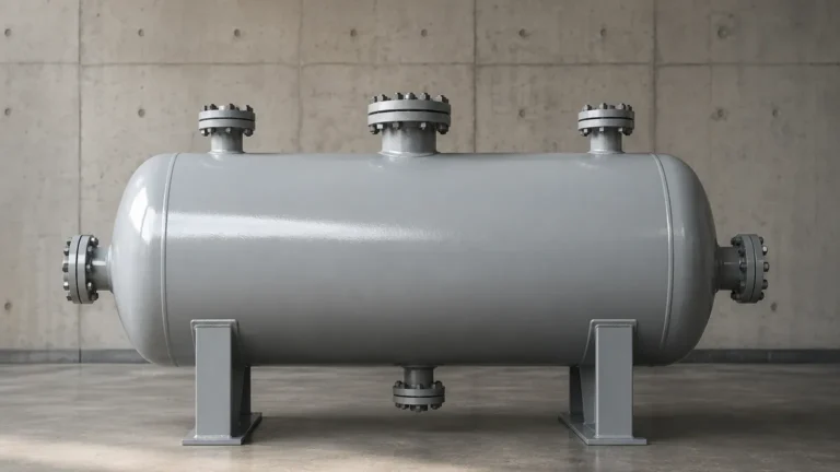
However, in many industrial applications, tanks are sealed and pressurized with an inert gas (like nitrogen) or contain vapors from the process liquid. In these closed systems, a single sensor at the bottom would measure the sum of the liquid's hydrostatic pressure and the gas pressure in the headspace. To isolate the liquid level, a second sensing point is required at the top of the vessel.
The Differential Equation
The core logic of differential sensing is defined by the equation:
$$\Delta P = P_{High} – P_{Low}$$
Where:
* $P_{High}$: The total pressure measured at the bottom of the vessel (liquid + headspace gas).
* $P_{Low}$: The pressure measured in the headspace (gas only).
* $\Delta P$: The resulting differential pressure, which represents the weight of the liquid column.
By subtracting the headspace pressure ($P_{Low}$) from the total pressure ($P_{High}$), the system provides a value that correlates strictly to the height of the liquid, regardless of whether the tank is under vacuum or high pressure. This principle is applied through various hardware configurations, ranging from traditional mechanical impulse lines to modern electronic systems. For those seeking specific hardware specifications and instrument types, the Main Page of industrial catalogs provides a starting point for comparing sensor architectures.
Comparison of Technologies: Traditional DP vs. Electronic Differential Sensing
Engineers typically choose between three primary methods for implementing differential sensing. Each has distinct advantages depending on the temperature, height, and chemical nature of the process.
1. Traditional Impulse Lines
This method uses small-diameter pipes (impulse lines) to connect the high and low pressure ports of a single differential pressure (DP) transmitter to the vessel.
* Wet Leg: The low-pressure line is filled with a reference liquid (often the process liquid or a stable condensate) to prevent vapors from condensing in the line and causing measurement drift.
* Dry Leg: The low-pressure line is kept dry and filled only with gas or vapor.
2. Remote Diaphragm Seals and Capillaries
In applications involving corrosive media, high temperatures, or hygienic requirements, remote seals are used. A flexible diaphragm is mounted at the process connection, and the pressure is transmitted to the sensor via a capillary tube filled with a stable fluid (e.g., silicone oil). This keeps the transmitter away from harsh process conditions.
3. Electronic Differential Sensing
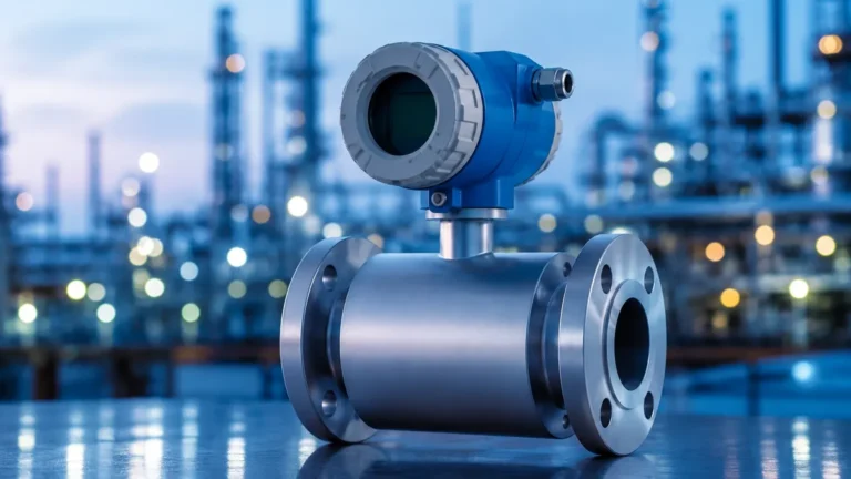
Modern digital transformation has led to the rise of electronic differential sensing. This system utilizes two independent pressure transmitters—one at the top and one at the bottom—connected via a digital cable. The "Master" sensor receives the signal from the "Remote" sensor and performs the subtraction electronically. This eliminates the need for impulse lines or oil-filled capillaries, which are prone to temperature-induced errors and mechanical failure.
Selection Comparison Table
| Feature | Impulse Lines | Remote Seals (Capillaries) | Electronic Differential Sensing |
| :— | :— | :— | :— |
| Primary Risk | Clogging, freezing, or leaking | Temperature-induced drift | Digital signal latency (minimal) |
| Installation | Complex piping/valving | Moderate; requires mounting | Simple; standard wiring |
| Maintenance | High (bleeding/cleaning) | Low | Very Low |
| Response Time | Fast | Moderate to Slow | Fast |
| Best For | Stable, clean fluids | Corrosive or hot media | Tall vessels and outdoor tanks |
Key Evaluation Criteria for Industrial Applications
When selecting a differential sensing solution, several technical factors must be evaluated to ensure long-term accuracy and reliability.
Static Pressure Limits
It is vital to distinguish between the differential pressure range (the height of the liquid) and the static pressure (the total pressure the vessel can reach). A sensor might be measuring a $\Delta P$ of only 500 mbar, but it may be doing so in a vessel pressurized to 40 bar. The instrument must be rated to withstand the maximum static pressure without shift or damage.
Material Compatibility
Since the sensing diaphragms are in direct contact with the process (or separated by a seal), material selection is paramount. Standard 316L stainless steel is common, but aggressive chemicals may require Hastelloy C, Monel, or Tantalum coatings. In the water treatment sector, specialized plastics or ceramics are often preferred for their resistance to oxidative chemicals.
Turndown Ratio and Accuracy
The turndown ratio refers to the range over which the sensor can be calibrated without losing significant accuracy. For example, a sensor with a 100:1 turndown can be adjusted to measure a very small liquid column even if its maximum capacity is much higher. In differential sensing, high accuracy is required because errors in either the high or low-side readings are compounded in the final calculation.

Installation and Engineering Considerations
Proper installation is often more critical than the choice of the sensor itself. Poorly designed sensing systems are the leading cause of "drift" in industrial level measurement.
Impulse Line Routing
For traditional DP systems, impulse lines should be sloped (typically 1:12) to allow gas bubbles to travel back to the tank (in liquid lines) or to allow condensate to drain back (in gas lines). In cold climates, these lines often require heat tracing and insulation to prevent the process fluid from freezing, which would effectively "lock" the measurement signal.
Capillary Temperature Effects
In remote seal systems, the fill fluid in the capillaries expands and contracts with changes in ambient temperature. If one capillary is in the sun and the other is in the shade, a false differential pressure will be created. Engineers must specify "temperature-compensated" systems or ensure that capillaries are routed together and shielded from direct sunlight and wind.
Electronic Leveling
When using electronic differential sensing, the physical distance between the two sensors can be significant (e.g., in a 20-meter silo). The system must be zeroed at the time of installation to account for the vertical distance and any slight offsets in sensor calibration. The advantage here is that the digital link is immune to the temperature fluctuations that plague oil-filled capillaries.
Limitations and Mitigation of Measurement Errors
While differential sensing is robust, it is not without limitations. Recognizing these boundaries allows for better system design.
1. Density Variations: Differential pressure measurement assumes a constant liquid density. If the temperature of the liquid changes significantly, its density changes, leading to a level error. This can be mitigated by using a multivariable transmitter that measures temperature and dynamically compensates the level calculation.
2. Foam and Turbulence: While DP sensors are less affected by surface foam than ultrasonic or radar sensors, extreme turbulence can cause "noise" in the pressure signal. Snubbers or software-based damping can be used to smooth the output.
3. Vacuum Service: In vacuum applications, the risk of "outgassing" in capillary fill fluids or the collapse of diaphragms is high. Specialized "gold-plated" diaphragms or specific fill fluids with low vapor pressure must be selected for these conditions.
Frequently Asked Questions (FAQ)
Q: Can differential sensing be used for flow measurement?
A: Yes. By placing an orifice plate or Venturi tube in a pipe, a differential pressure is created that is proportional to the square of the flow rate. The same DP transmitter used for level can often be reconfigured for flow.
Q: What is the advantage of a magnetic level gauge with differential sensing?
A: Some systems combine a magnetic level gauge (for local visual indication) with a differential pressure transmitter for remote monitoring. This provides redundancy, allowing operators to verify the electronic signal against a physical float-based indicator.
Q: How often should differential sensing instruments be calibrated?
A: Most modern instruments from manufacturers like Welk are designed for high stability. However, in critical safety loops (SIL rated), annual calibration or proof testing is standard. For general process monitoring, a check every 2 to 3 years is often sufficient unless drift is detected.
Q: Is differential sensing better than radar for pressurized tanks?
A: Not necessarily. Radar is non-contact and unaffected by density, but it can be challenged by internal tank obstructions or very low dielectric constants. Differential sensing is often more cost-effective and is a "mechanical" measurement of mass, which is preferred in many custody transfer or high-pressure chemical applications.
By adhering to these engineering principles and carefully selecting the hardware configuration—whether it be traditional DP or modern electronic differential sensing—operators can ensure precise control over their liquid assets. For a deeper look at specific instrument models and technical data sheets, professionals are encouraged to review the Main Page of authoritative industry suppliers to match technology to their specific environmental constraints.