Emerson Vortex Flow Meter
Emerson Vortex Flow Meter
In the landscape of industrial process control, the Emerson vortex flow meter, specifically the Rosemount 8800 series, has established itself as a benchmark for reliability and versatility. Designed to measure the flow of liquids, gases, and steam, these instruments are critical in applications where durability and a lack of moving parts are prioritized. While level measurement remains a cornerstone of inventory management—often handled by specialized instruments found on our Main Page—flow measurement provides the dynamic data necessary for real-time process optimization and mass balance calculations.
This guide examines the technical foundations of vortex shedding technology, the specific engineering advantages of the Emerson design, and the practical considerations required for successful deployment in heavy industrial environments.
Understanding the Vortex Shedding Principle
The operation of an Emerson vortex flow meter is based on the Von Kármán effect. This physical phenomenon occurs when a fluid (liquid or gas) flows past a non-streamlined object, known as a "bluff body" or "shedder bar."
As the fluid strikes the shedder bar, it cannot follow the sharp contours of the object. This causes the fluid to separate from the surface of the bar, creating alternating low-pressure areas known as vortices. These vortices are shed in a staggered, periodic pattern. The frequency at which these vortices are shed is directly proportional to the velocity of the fluid moving through the pipe.
The Mathematical Foundation
The relationship between flow velocity and shedding frequency is defined by the Strouhal Number ($St$), a dimensionless parameter. The formula is generally expressed as:
$$f = \frac{St \times V}{d}$$
Where:
* $f$ is the vortex shedding frequency.
* $St$ is the Strouhal number (constant for a specific bluff body shape over a wide range of Reynolds numbers).
* $V$ is the velocity of the fluid.
* $d$ is the width of the shedder bar.
By measuring the frequency of the pressure fluctuations caused by the vortices using a piezoelectric sensor, the meter calculates the flow velocity. When combined with the known cross-sectional area of the pipe, the instrument provides an accurate volumetric flow rate.
Key Features of the Emerson Vortex Flow Meter Series
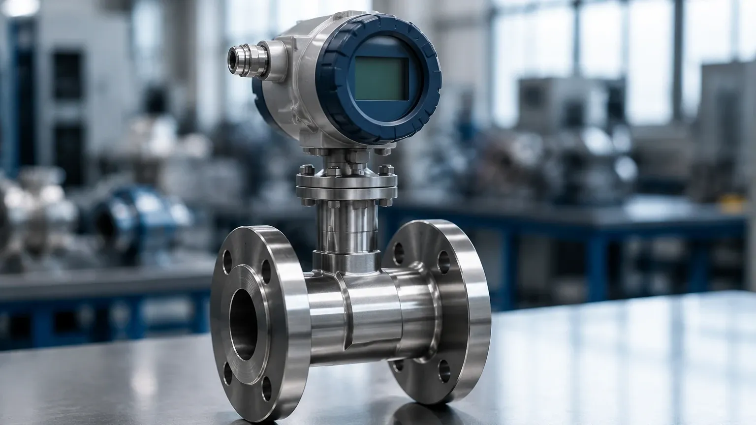
The Emerson Rosemount 8800 series is distinguished by several engineering choices that address common failure points in flow measurement. Unlike traditional vortex meters that may use O-rings or internal seals, the Emerson design focuses on a robust, all-welded construction.
Non-Clog, Gasket-Free Design
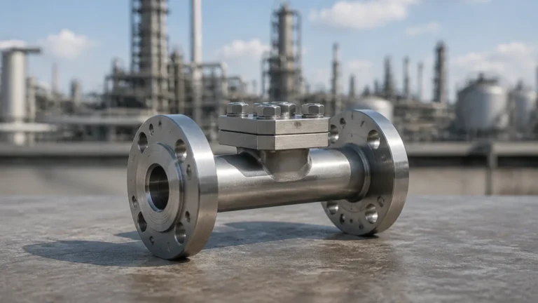
One of the primary advantages of the 8800 series is its gasket-free meter body. In many industrial processes, gaskets are a point of weakness, prone to degradation from corrosive chemicals or extreme temperatures. By utilizing an all-welded design, the Emerson vortex flow meter eliminates potential leak paths and reduces maintenance requirements. This is particularly beneficial in high-pressure steam applications where seal failure can lead to significant safety risks.
Isolated Sensor Technology
In many vortex designs, the sensor is in direct contact with the process fluid. If the sensor fails, the process must be shut down and the pipe drained to facilitate a replacement. Emerson utilizes an isolated sensor design. The piezoelectric sensor is located outside the process flow, separated by a diaphragm. This allows for sensor replacement without breaking the process seal, significantly increasing uptime in continuous manufacturing environments.
MultiVariable Capability
Modern Emerson vortex flow meters often include MultiVariable options. These units integrate a temperature sensor directly into the meter body. For steam and gas applications, where density changes significantly with temperature, the meter can provide compensated mass flow readings. This eliminates the need for a separate temperature transmitter and a flow computer, simplifying the installation and reducing the overall footprint of the measurement point.
Technical Specifications and Selection Criteria
Selecting the correct flow meter requires a detailed understanding of the process fluid and the piping environment. The following table provides a comparison of typical specifications for vortex meters compared to other technologies often used alongside level measurement solutions.
| Feature | Emerson Vortex Flow Meter | Ultrasonic Level Meter (Welk) | Radar Level Meter (Welk) |
| :— | :— | :— | :— |
| Primary Measurement | Flow Velocity / Volumetric Flow | Distance to Surface / Level | Distance to Surface / Level |
| Fluid State | Liquid, Gas, Steam | Liquid, Slurries | Liquid, Solids, Corrosives |
| Moving Parts | None | None | None |
| Standard Accuracy | ±0.65% (Liquids) | ±0.25% of Range | ±1 mm to ±3 mm |
| Process Temp Range | -200°C to +427°C | -40°C to +80°C | -40°C to +250°C+ |
| Max Pressure | Up to ANSI 2500# | Atmospheric (Typical) | Up to 160 bar |
| Installation Type | In-line (Flanged/Wafer) | Top-mounted (Non-contact) | Top-mounted (Non-contact) |
Material Selection
For corrosive environments, Emerson offers various alloys. While 316L stainless steel is the standard for most water and steam applications, Nickel Alloy (Hastelloy) options are available for aggressive chemical processing. It is vital to match the shedder bar and meter body material to the chemical compatibility of the fluid to prevent premature erosion or stress corrosion cracking.
Installation Guidelines for Optimal Performance
To achieve the stated accuracy of an Emerson vortex flow meter, strict adherence to installation geometry is required. Because the meter relies on a stable flow profile to generate consistent vortices, turbulence upstream of the meter must be minimized.
Straight Pipe Requirements
* Upstream: A minimum of 10 to 35 nominal pipe diameters (D) of straight pipe is typically required, depending on the presence of elbows, valves, or reducers upstream.
* Downstream: At least 5 nominal pipe diameters (D) of straight pipe should follow the meter to prevent back-pressure fluctuations from affecting the vortex shedding.
If the required straight runs cannot be met, flow straighteners or vanes may be necessary to condition the flow profile before it reaches the shedder bar.
Orientation and Piping
* Liquid Service: The pipe must remain full at all times. For this reason, vertical upward flow is preferred. If horizontal installation is used, the meter should be placed at a low point in the piping to ensure it does not trap gas.
* Gas/Steam Service: In horizontal pipes, the meter should be installed such that condensate does not pool around the shedder bar. For steam, proper lagging (insulation) of the pipe and meter body is essential to prevent excessive condensation and thermal shock to the electronics.
Vibration Mitigation
Because vortex meters use piezoelectric sensors to detect pressure pulses, they can be sensitive to mechanical pipe vibration. Emerson’s "Mass Balanced" sensor design helps filter out common-mode vibration, but it is still best practice to support the piping on both sides of the meter in high-vibration environments.
Limitations and Common Application Risks
While highly versatile, the Emerson vortex flow meter is not a universal solution. Engineers must be aware of specific limitations:
1. Low Flow Cutoff (Reynolds Number): Vortex meters require a minimum fluid velocity to generate detectable vortices. If the flow rate drops below a certain Reynolds number (typically 10,000 to 20,000), the meter will read zero, even if there is some movement in the pipe. It is not suitable for very low-velocity applications.
2. Viscosity Constraints: High-viscosity fluids dampen vortex formation. Generally, vortex meters are limited to fluids with a viscosity of less than 8 to 10 centipoise (cP).
3. Cavitation: In liquid applications, if the pressure drop across the meter causes the local pressure to fall below the vapor pressure of the liquid, cavitation occurs. This can damage the shedder bar and result in highly inaccurate readings.
4. Abrasive Fluids: While the shedder bar is robust, fluids with high concentrations of abrasive solids can wear down the sharp edges of the bar over time. As the bar rounds off, the Strouhal number changes, leading to a drift in calibration.
Integrating Flow and Level Measurement Systems
In many B2B industrial scenarios, such as chemical tank farms or water treatment facilities, flow and level measurements are used in tandem. For example, while a Welk radar level meter provides the precise volume of liquid remaining in a storage tank, an Emerson vortex flow meter on the outlet line monitors the rate of consumption.
Integrating these data points allows for:
* Leak Detection: Comparing the change in tank level against the totalized flow measured by the vortex meter.
* Pump Control: Using flow rates to prevent pump cavitation or dry-running, while level sensors provide the primary start/stop signals.
* Mass Balance: In steam systems, measuring the feedwater level in the boiler while simultaneously measuring the steam output flow to calculate boiler efficiency.
For engineers looking to optimize these integrated systems, reviewing the full range of level measurement technologies on our Main Page is a recommended next step to ensure sensor compatibility.
Frequently Asked Questions (FAQ)
Q: Can an Emerson vortex flow meter measure bi-directional flow?
No. Vortex meters are inherently uni-directional. The shedder bar and sensor are optimized for flow from a specific direction. Reversing the flow will result in no signal or highly inaccurate data.
Q: How often does the meter need to be calibrated?
Because there are no moving parts to wear out, the "K-factor" (the relationship between pulses and volume) remains stable over many years. Most facilities perform a loop check or electronics verification annually, but physical recalibration is usually only necessary if the shedder bar has been damaged by erosion or corrosion.
Q: Is it possible to use a vortex meter on compressed air?
Yes, vortex meters are excellent for compressed air. However, it is crucial to use a MultiVariable version or external pressure/temperature compensation, as compressed air is highly compressible, and mass flow is usually the required metric for energy audits.
Q: What is the difference between a Wafer and a Flanged body style?
Wafer meters are "sandwiched" between existing pipe flanges, making them lighter and more cost-effective. Flanged meters have their own bolt circles and are generally preferred for high-pressure applications or where frequent removal is required, as they provide a more robust mechanical connection.
Conclusion
The Emerson vortex flow meter represents a sophisticated balance of physics and industrial engineering. By eliminating moving parts and providing a robust, all-welded measurement solution, it addresses the core needs of modern process industries—reliability, safety, and accuracy. When properly selected and installed according to the guidelines regarding straight pipe runs and fluid properties, these meters provide years of maintenance-free service. For comprehensive process control, combining these flow insights with the advanced level measurement solutions available on our Main Page ensures a complete and accurate picture of industrial fluid dynamics.